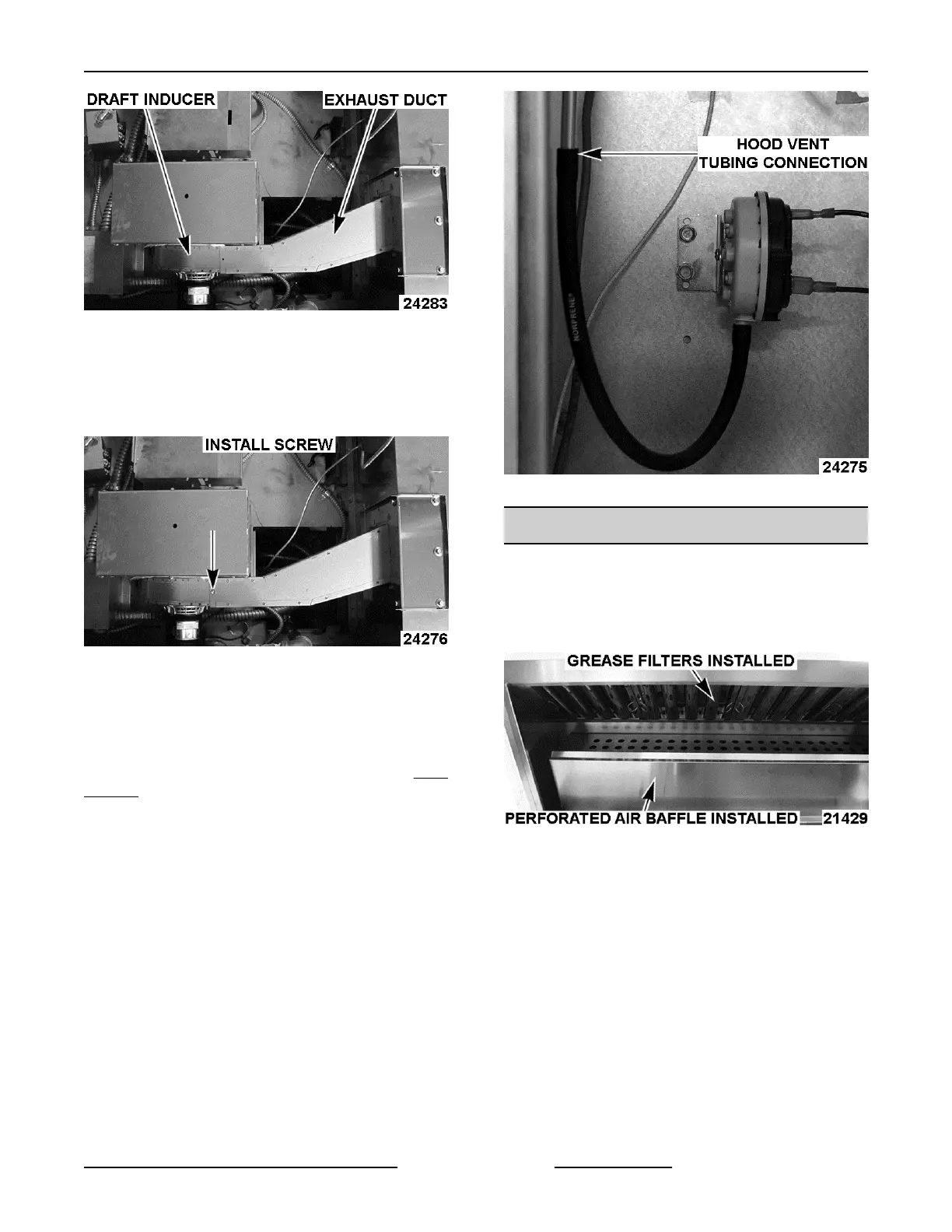
Fig. 120
3. Secure exhaust duct to exhaust connection
plate.
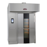
4. Secure exhaust duct with #10 Tek screws to draft
inducer.
Fig. 121
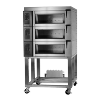
5. Connect
the hood exhaust tube at hood exhaust
pressure switch. Switch location on side of
control panel inside control compartment. Leave
tubing coiled in control compartment.
NOTE: Defer connecting hood vent tube to the
hood
exhaust connection until start up.
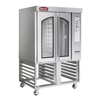
Fig. 122
AIR BAFFLE & GREASE FILTERS
1. Install perforated air baffle with 1/4-20 acorn
nuts.
2. Install grease filters for type 1 hood or install
perforated plenum panel for type 2 hood.
Fig. 123
INSTALLATION INSTRUCTIONS OV500-EE SERIES GAS RACK OVENS AND OV500 SERIES ELECTRIC RACK
OVENS - INSTALLING OVEN
Page 43 of 49 F45469 Rev. D (1019)