Deviation, now laser head is required to adjust. In this process, the object lens moves forwards or
Backwards, and the moving range is very small.
(3) FMO: similar to acts of trace, the acts of feed are larger than those of trace. Feed conducts a
large scale movement firstly, and then trace moves slightly in this range. Feed moves for a while, and
does not move for another while; but trace moves all the time. Feed is rough adjustment and trace is fine.
The acts are obvious when opening and selecting track.
(4) DMO: it is the performance agency for main axis disc rotation. Its rotation speed decides that of
disc. Its rotation is generated by an individual DC electric machine, in which rotation speed of DVD is
twice over that of CD.
3.2.3 Laser power control circuit
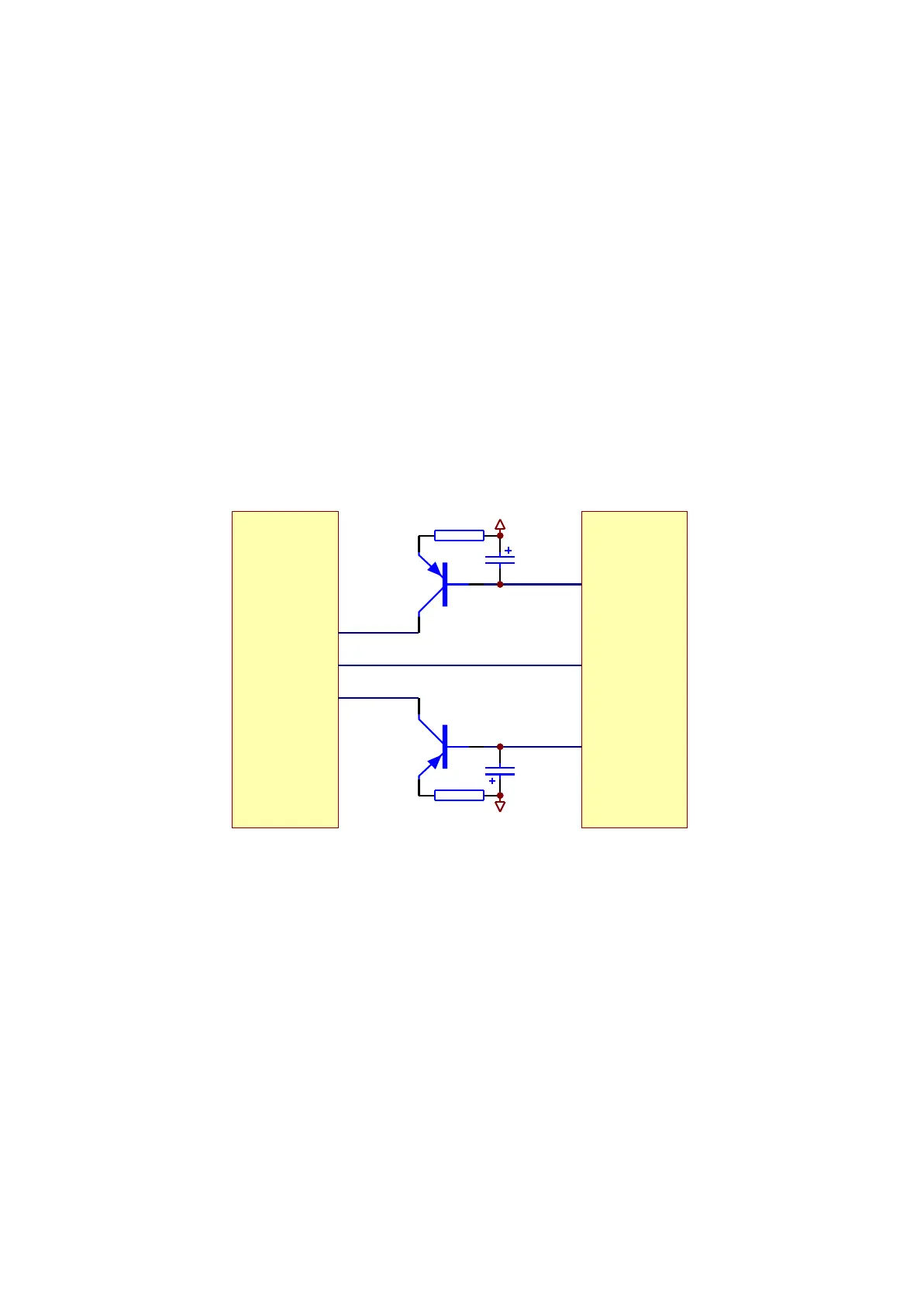
1. Laser power control circuit is shown as in the following figure 3.2.3.1:
Q301
2SB1132-S
Q302
2SB1132-S
R301
4.7R
R302
4.7R
TC302
47uF/16V
TC303
47uF/16V
LDO-AV33
LDO-AV33
LDO2
LDO1
MT1389E
MD1
20/21
XS301
23
20
19
2. Working principle
Pin 20/21 of MT1389 is laser power detect signal input pin, pin 21 is DVD laser power strong/weak
detect signal input pin, pin 23 is VCD laser power drive control output pin, pin 22 is DVD laser power
drive control output pin.
When reading VCD disc, laser power becomes weak, voltage of MDII pin decreases, voltage
decrease of pin 23 of MT1389 makes voltage of pin 19 of XS301 increase to reach the purpose of raising
laser power. When laser power is too strong, voltage of MDII pin increases to lead to voltage of pin 23 of
MT1389 increase to make voltage of pin 19 of XS301 decrease to reach the purpose of reducing laser
power to form an auto power control circuit.
Figure 3.2.3.1 Laser power control circuit diagram
- 19 -