Key point Position Voltage Remark
DV33 (point A) Diode VD201 cathode 3.3V
TC217 may sends out current from this
point after power failure
Point B Diode VD201 anode
3.3V after reset
finishes
After reset finishes, voltage increases from
0V to 3.3V
Point C Pin 5 of reverter 0V after reset finishes
After reset finishes, voltage decreases from
3.3V to 0V
URST# (point D)
Connection place of
R256 and R253
3.3V after reset
finishes
After reset finishes, voltage increases from
0V to 3.3V
3. Working principle: MT1389 has a comparator inside composed of operational amplifier, in which
OP+ is the in-phase input end of operational amplifier, OP- is reverse input end, OPO is output end,
when playing disc normally, for electric machine is positive direction rotating, voltage of OP+ is higher
than that of OP-, voltage of OPO is more than 1.4V. When disc out is needed, main axis drive signal
stops, for electric machine is permanent magnetic, when in rotating, induced electromotive force
produces in two ends to give to decode chip through R320, R319 sampling to make OPO output less
than 1.4V voltage and transmit to input pin of MT1389 ADIN through R318. When ADIN is high level,
main axis drive output end has not any drive signal output, when ADIN is low level, MT1389 outputs a
reversing drive signal to main axis drive circuit to make main axis electric machine speed down. Thus
circular working goes on until main axis stops rotating. PDVD is manual disc out means, so after disc out,
disc is still rotating, but will stop very son.
4. Key point voltage (unit: V) is shown as the following table:
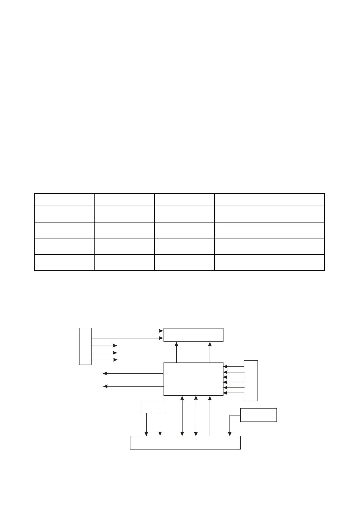
3.2.5 Control panel circuit
1. Control panel circuit block diagram is shown in the following figure 3.2.5.1:
Figure 3.2.5.1 Control panel circuit block diagram
VFD screen
Grid1~Grid8
S0793
D ATA
CLOCK
STB
X S401
Remote control
receiver
KEY1
KEY2
Button
Seg2~Seg16
IR
Seg3
Seg2
Seg4
Seg5
Volume
knob
J3
J4
FL+
FL-
D+5V
-21V
DGND
LED2
LED1
XS 201
- 21 -