Name
When reading
disc normally
When disc out When disc in
When no
disc in
TROPEN 0
There is about 1 second 3.3V
pulse when at the moment of disc
out
0 0
TRCLOSE 0 0V
There is about 1 second 3.3V pulse
when at the moment of disc out
0
TROUT 3.41V
3.3V 0V 0V 3.3V
3.3V
TRIN 0
0V 3.3V 3.3V 0V
0
OPO 2.61V 2.75V 2.64V 2.61V
ADIN 2.61V 2.76V 2.61V 2.61V
OP+ 1.66V 1.81V 1.27V 1.81V
OP- 1.85V 2.12V 1.47V 2.04V
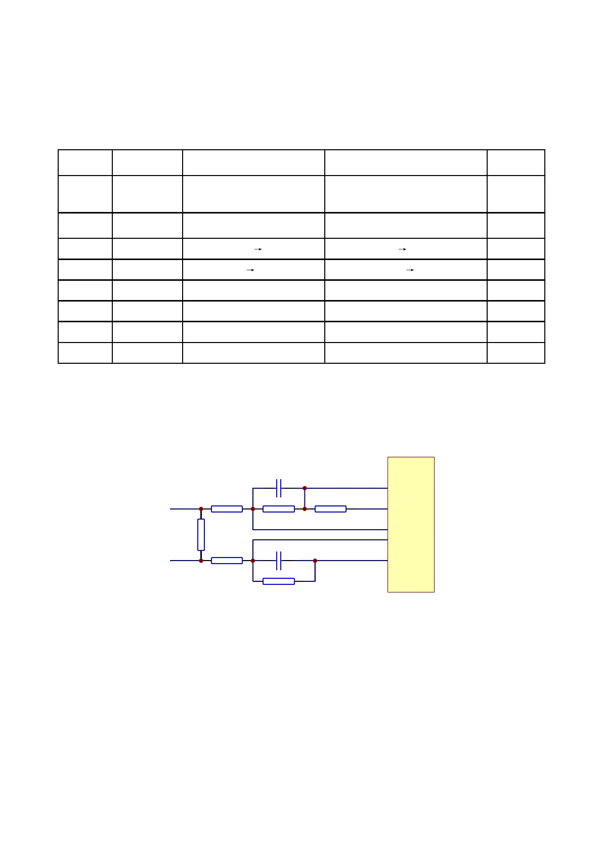
3.2.4 Main axis control circuit
1. Main axis control circuit is shown as in the following figure 3.2.4.1:
R321
1R
R320
150K
R319
150K
R322 680K
R317 680K
R318
0R
C307 222
ADIN
OP-
OP+
V1P4
SP-
OPO
C308 222
SPL-
MT1389
Figure 3.2.4.1 Main axis control circuit diagram
2. Function: disc is always in high speed rotation in the course of disc reading, when you need to
open the door to change disc, MT1389 stops the positive direction drive signal which is given to main
axis drive circuit, for the function of inertia disc is still rotating. If disc out order is performed at this time,
disc will be abrasively damaged. Therefore, machine must be baking to main axis, that whether disc has
stopped rotating and whether disc is reversing, decode chip of the machine cannot recognize. So a main
axis control circuit is added to make decode chip can effective monitor that whether disc has stopped
rotating.
When reading DVD disc, pin 21 is detect signal input pin, pin 22 is drive control input pin, and the
working principle is the same with that when playing VCD disc.
3. Key point voltage (unit: V) is shown as the following table:
- 20 -