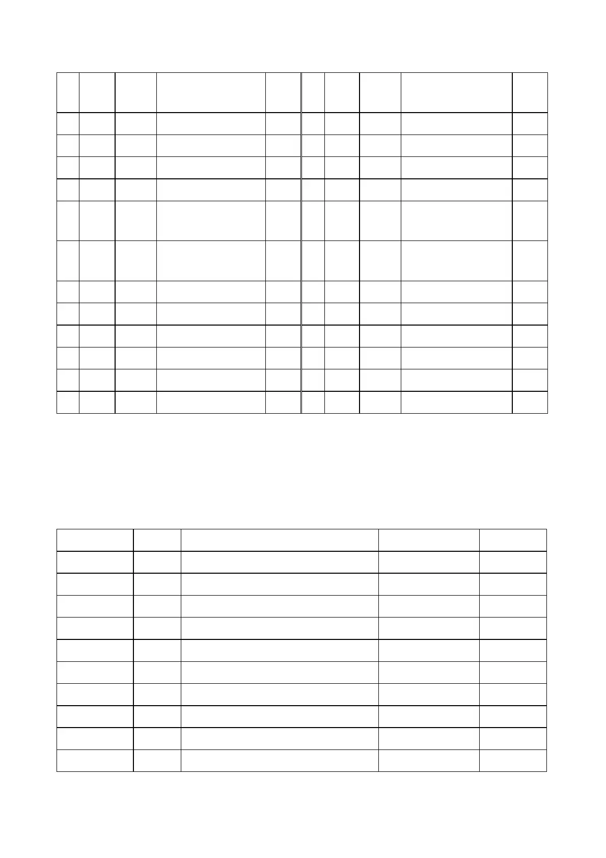
15
LDQM
I
Data in/out screen-shielded
signal
2.46 42
DQ8
I/O Data bus 0.6
16
WE I Write control signal 3.17 43
VDDQ
3.3V power supply 3.19
17
CAS I Line address gating signal
3.01 44
DQ9
I/O Data bus 0.91
18
RAS I Row address gating signal
3.13 45
DQ10
I/O Data bus 0.8
19
CS I Chip selection signal 2.95 46
VSSQ
Ground 0.01
20
SD-BS0
I
Section address 0 gating
signal
1.8 47
DQ11
I/O Data bus 0.79
21
SD-BS1
I
Section address 1 gating
signal
2 48
DQ12
I/O Data bus 1.16
22
MA10
I Address bus 0.04 49
VDDQ
3.3V power supply 3.19
23
MA0 I Address bus 0.36 50
DQ13
I/O Data bus 1.15
24
MA1 I Address bus 0.35 51
DQ14
I/O Data bus 1.24
25
MA2 I Address bus 2.38 52
VSSQ
Ground 0.01
26
MA3 I Address bus 1.59 53
DQ15
I/O Data bus 0.68
27
VDD
3.3V power supply 3.19 54
VSS
Ground 0.01
3.5.3 Function introduction to FLASH
FLASH (U214) is a 16Mbit FLASH memorizer, and the damage of U214 may cause troubles, such as
power not on, no disc reading and power on picture mosaic. Pin function is shown as the following table:
Pin Name Function Voltage (when no disc)
Data direction
1-9、16-25、48
AO-A19
20 bit address bus I
11 WE Write enable signal, low level is effective 3.23V I
12 RESET
Reset, low level is effective 3.23V I
10、13、14 NC Blank pin
15 RY/BY Ready/system busy 3.23V O
26 CE Chip enable, low level effective 0V I
27、46 VSS Ground
28 OE Output enable signal , low level is effective 0V I
29-3、6、38-44
DQ0-DQ14
15 bit data bus O
37 VCC 5V power supply +5V
- 78 -