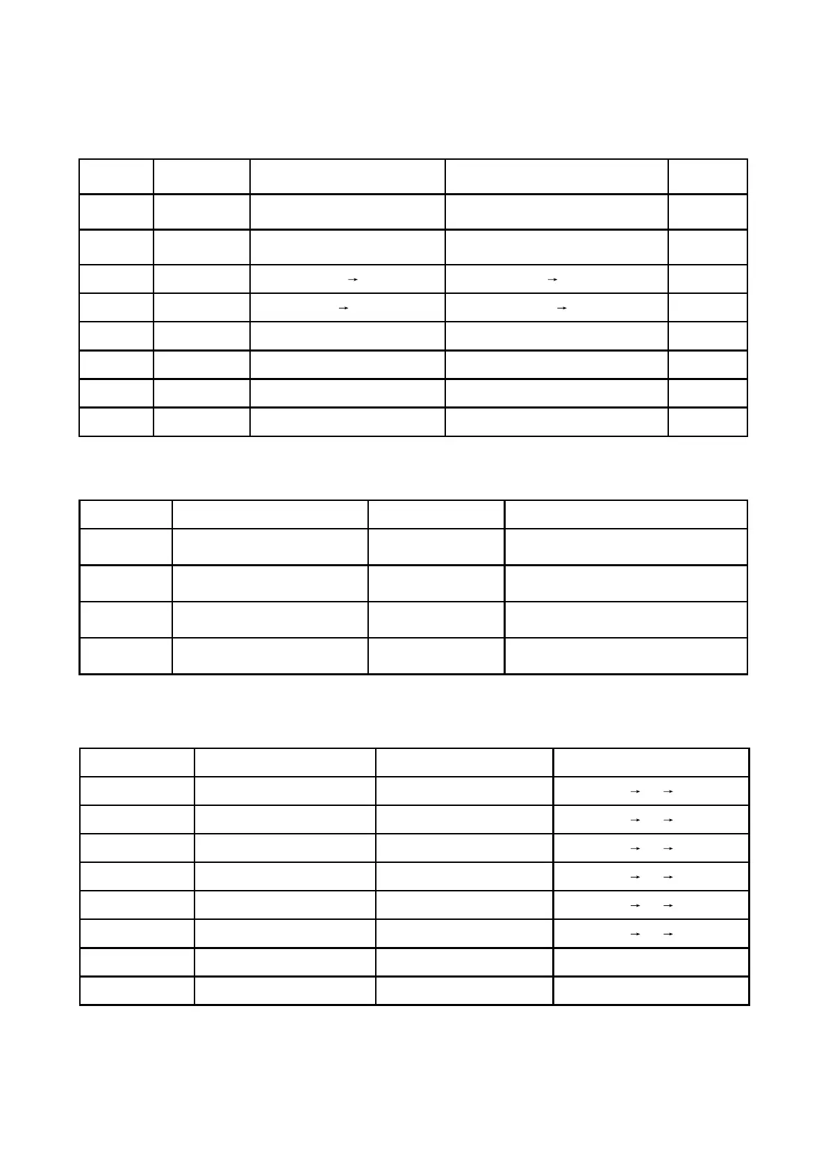
2. Key point voltage is shown as the following table:
3.4.2 Key point voltage
1. Voltage of key point is shown as follows:
Key point Position Voltage Remark
DV33 (point A) Diode VD201 cathode 3.3V
TC217 may sends out current from this point
after power failure
Point B Diode VD201 anode 3.3V after reset finishes
After reset finishes, voltage inc reases from 0V
to 3.3V
Point C Pin 5 of reverter 0V after reset finishes
After reset finishes, voltage decreas es from
3.3V to 0V
URST# (point D) Connection place of R256 and R253 3.3V after reset finishes
After reset finishes, voltage inc reases from 0V
to 3.3V
Name
When reading disc
normally
When disc out When disc in
When no disc
in
TROPEN 0
There is about 1 second 3.3V pulse
when at the moment of disc out
0 0
TRCLOSE 0 0V
There is about 1 second 3.3V pulse when at
the moment of disc out
0
TROUT 3.41V
3.3V 0V 0V 3.3V
3.3V
TRIN 0
0V 3.3V 3.3V 0V
0
OPO 2.61V 2.75V 2.64V 2.61V
ADIN 2.61V 2.76V 2.61V 2.61V
OP+ 1.66V 1.81V 1.27V 1.81V
OP- 1.85V 2.12V 1.47V 2.04V
3. Key point voltage (unit: V), shown as the following table:
Key point Position Normal working voltage (V) Voltage change when disc out (V)
SP+ Pin 11 of D5954, pin 5 of XS303 3.79
3.79 0.70 1.80
SP- Pin 12 of D5954, pin 6 of XS303 1.38
1.38 3.40 1.80
OP+ Pin 36 of MT1389/B 1.38
1.38 3.10 1.80
OP- Pin 35 of MT1389/A 1.53
1.53 3.08 1.98
OPO Pin 34 of MT1389/C 2.44
2.44 0.40 2.50
ADIN Pin 47 of MT1389/D 2.44
2.41 0.41 2.44
DMSO Pin 5 of D5954 1.42 1.42
VIP4 Pin 30 of MT1389 1.41 1.41
- 61 -