TX1500 Manual V3.5 Dec 07 Page 14 of 40 TX1500/AL16 16 INPUT ALARM CARD
TX1500/AL16 - 16 ALARM INPUT CARD
Each alarm card provides 16 individual normally closed volts free alarm inputs. The card communicates via the BBUS
with the monitor output card. Power is supplied either via the BBUS interface when the alarm card is mounted in the
TX1500 subrack or via an external 9Vdc supply when mounted remotely.
NOTE: Only 1 alarm card can be powered from the BBUS port.
The power led is used as a status indication and shows the following:
Mainly ON, flashing OFF when the alarm card is polled, approx 2-3 times every second. (NORMAL)
OFF permanently – alarm card not powered or faulty.
ON permanently – Not polled by MONITOR card, BBUS cable faulty or ALARM card faulty.
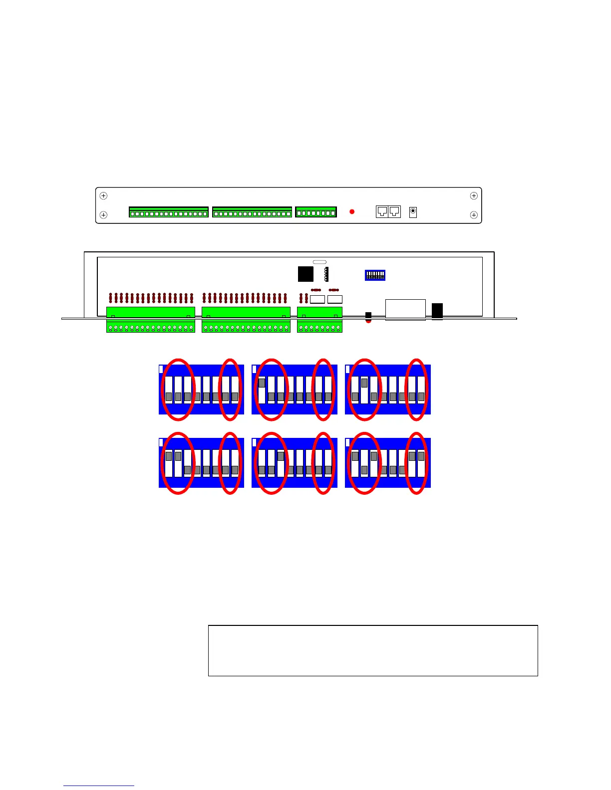
Fig 23. Alarm card front panel view
Fig 24.
Alarm
card
internal
view
Fig 25. Alarm card SW1 address switch settings
Each alarm card has two single pole changeover relays called Relay 1 and Relay 2. These relays can be driven
manually and also from alarm activations. The system relay numbers are assigned as follows:
Alarm Card Relay 1 Relay 2
1 1 2
2 3 4
3 5 6
4 7 8
5 9 10
6 11 12
B-BUS
ALARM INPUT 1-8 ALARM INPUT 9-16
OUTPUTS
12Vdc
12 3456 78
ON
SW1 is used to set the alarm card address as follows:
12 3456 78
ON
12 3456 78
ON
12 3456 78
ON
12 3456 78
ON
12 3456 78
ON
Card 1 alarm 1-16 Card 2 alarm 17-32 Card 3 alarm 33-48
Card 4 alarm 49-64 Card 5 alarm 65-80 Card 6 alarm 81-96
Switches 7 & 8
BBUS RS485 Termination
ON = Terminated
OFF = Un-terminated
Must be ON if the alarm card is at
the end of line and OFF otherwise.
Alarm card 6 shown as end of line.
02002
SW1
LD1
B-BUS
RY2 RY1
J1
Note: alarm card relay 1 cannot be controlled from the keyboards as it is an
alarm output contact that changes state when any alarm becomes active.
This allows it to be used to switch a VCR into realtime recording etc. The
duration is set in the matrix menu.
Rela
1 Time