TX1500 Manual V3.5 Dec 07 V2 Page 6 of 40 TX1500 MATRIX
BBUS CONTROL BUS
The TX1500 communicates with all keyboards, alarm cards and BBUS-IF interfaces via a polled 4 wire multidrop
RS422 control bus named BBUS.
All the units are equipped with standard RJ45 connectors allowing cat 5 patch cables to be used to connect over
short distances. On the larger sites RJ45 break out boxes are used to link between cat 5 cables and good
quality screen twin twisted pair data cable. Suitable types are the following Belden cables: 9842, 9829, 8162,
8132.
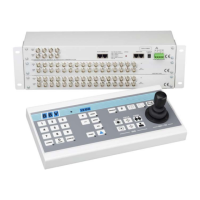
1 = DO NOT USE (+V)
2 = DO NOT USE (+V)
3 = RxA to MONITOR CARD
4 = TxA from MONITOR CARD
TxB from MONITOR CARD = 5
RxB to MONITOR CARD = 6
(0V) SCREEN = 7
(0V) SCREEN = 8
(BLUE)
(GREEN/WHITE)
(GREEN)
(BLUE/WHITE)
Fig 5. BBUS - RJ45 breakout box connector, MONITOR CARD end of BBus.
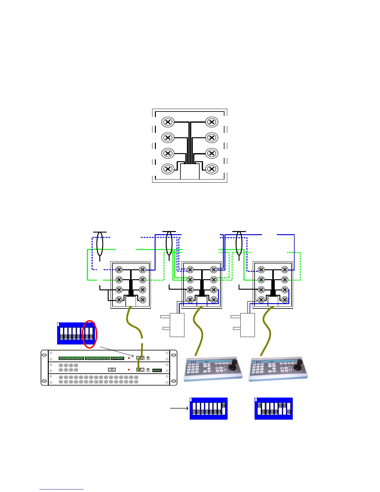
Fig 6. Keyboard BBUS wiring
0V +9Vdc 0V +9Vdc
RJ45 patch cable max length = 2M
Rx Data (TO CPU)
Tx Data (FROM CPU)
BBUS maximum distance 1200M end-to-end
Keyboard 1
BBUS Un-Terminated
Keyboard 2
BBUS Terminated
Alarm card
BBUS Un-Terminated
Switch 7-8 OFF
12 3456 78
ON
Card 1 alarm 1-16
12 3456 78
ON
12 3456 78
ON
1-5 = Keyboard Address
6&7 = BBUS termination
8 = Program Key Enable
SCREEN
SCREEN
SCREEN
BLUE
GREEN/WHITE
BLUE/WHITE
GREEN