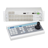
TX1500 Manual V3.5 Dec 07 Page 8 of 40 TX1500 MATRIX
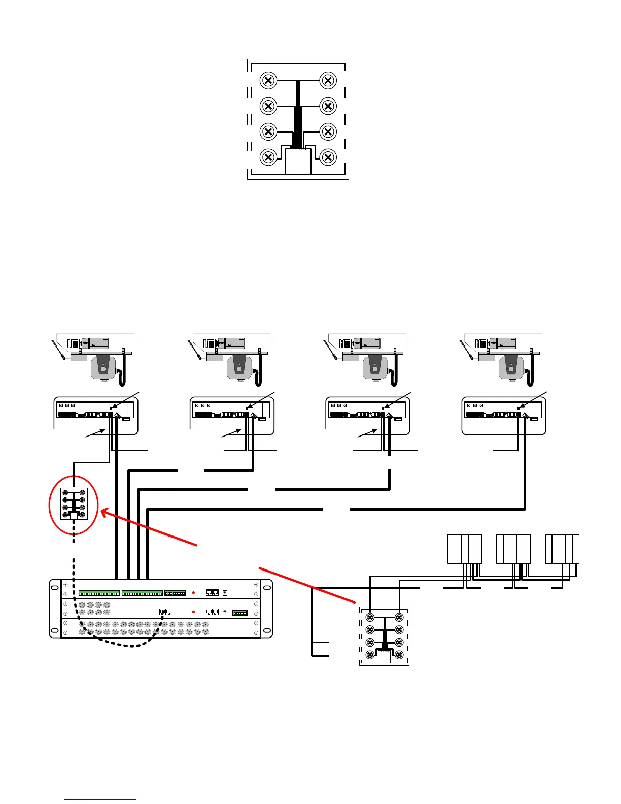
RS485 TELEMETRY OUT
Fig 10. TELEMETRY – RJ45 breakout box connector.
This port provides telemetry control via BBV RS485. Again a Cat 5 RJ45 patch cable and breakout box is used to
connect the telemetry receivers via single twisted pair cable. It is possible to either wire the network in a daisy
chained or star configuration using an optional RS485 star card.
RS485 wiring configurations are shown below and on the following page.
RS485 TELEMETRY WIRING CONFIGURATIONS
Fig 11. Daisy Chained RS485 Telemetry Wiring
1 = DO NOT USE
2 = DO NOT USE
3 = DO NOT USE
4 = TxA to Telemetry Receiver RA(+)
TxB to Telemetry Receiver RB(-) = 5
DO NOT USE = 6
GROUND/SCREEN = 7
GROUND/SCREEN = 8
(BLUE)(BLUE/WHITE)
1 = DO NOT USE
2 = DO NOT USE
3 = DO NOT USE
4 = TxA to RA (+)
TxB to RB (-) = 5
DO NOT USE = 6
SCREEN = 7
SCREEN = 8
Camera 1 Camera 2 Camera 3 Camera 4
Rx45X/55X Address 1 Rx45X/55X Address 2 Rx45X/55X Address 3Un-Terminated Un-Terminated Un-Terminated
RS485 Telemetry
Coax
Coax
RS485 Telemetry RS485 Telemetry
Terminated
Rx45X/55X Address 4
Coax
Rx457/557 RS485 connectors
screen
T
R
A
T
R
B
G
N
D
R
A
R
B
screen
T
R
A
T
R
B
G
N
D
R
A
R
B
Keep stub length as
short as possible
Keep stub length as
short as possible
RJ45 breakout box
Keep stub length as
short as possible
screen
T
R
A
T
R
B
G
N
D
R
A
R
B
D
E
T
A
I
L
E
D
V
I
E
W
RJ45 patch cable
Maximum length of RS485 from Tx1500 to last receiver - 1200M