7
Contents
Chapter 1: System Setup ..............................................................................................11
1.1 Welcome! ......................................................................................................................................11
1.2 Packing Contents..........................................................................................................................11
1.3 Special Features ...........................................................................................................................12
1.3.1 Product Highlights.........................................................................................................................12
1.4 Before you proceed.......................................................................................................................14
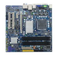
1.5 Mainboard Overview .....................................................................................................................15
1.5.1
Placement direction ......................................................................................................................15
1.5.2 Screw Holes ..................................................................................................................................15
1.5.3 Mainboard Layout .........................................................................................................................16
1.6 Central Processing Unit (CPU) .....................................................................................................17
1.6.1 Installing the CPU .........................................................................................................................18
1.6.2 Installing the CPU Heatsink and fan .............................................................................................20
1.6.3 Uninstalling the CPU Heatsink and fan.........................................................................................22
1.7 System Memroy ............................................................................................................................24
1.7.1 Overview.....................................................................................................................................24
1.7.2 Dual-Channel Mode Population Rule .....................................................................................24
1.7.3 Installing DIMM .............................................................................................................................25
1.7.4 Removing a DIMM
...................................................................................................26
1.8 Power Supply................................................................................................................................27
1.8.1 ATX 24-pin Power Connector: JPWR3.........................................................................................27
1.8.2 ATX 12V Power Connector: JPW1 ...............................................................................................27
1.9 Back Panel ....................................................................................................................................29
1.10 Connectors/Headers .....................................................................................................................31
1.10.1
Floppy Disk Drive Connector: FDD1.............................................................................................31
1.10.2 IDE Connector: IDE1 ....................................................................................................................31
1.10.3 Serial ATA Connectors: SATA1, SATA3, SATA4, SATA5, SATA2..............................................32
1.10.4 Fan Power Connector: CPUFAN1, SYSFAN1..............................................................................32
1.10.5 Chassis Intrusion Switch Header: JCI1 ........................................................................................33
1.10.6 CD-In Connector: JCD_IN1 ..........................................................................................................33
1.10.7 Front Panel Audio Connector: JAUD1....................................................................................33
1.10.8 Front USB Connectors: JUSB1, JUSB2, JUSB3..........................................................................34
1.10.9 Serial Port Connector: JCOM1 .....................................................................................................34