75.5695.08 IS40 IS40XL 20230627 Page 3 of 8
1
2
3
POWER SUPPLY
12 – 24 VAC/VDC
1-4
15° 30° 45°
15° 30° 45°
1
2
1
2
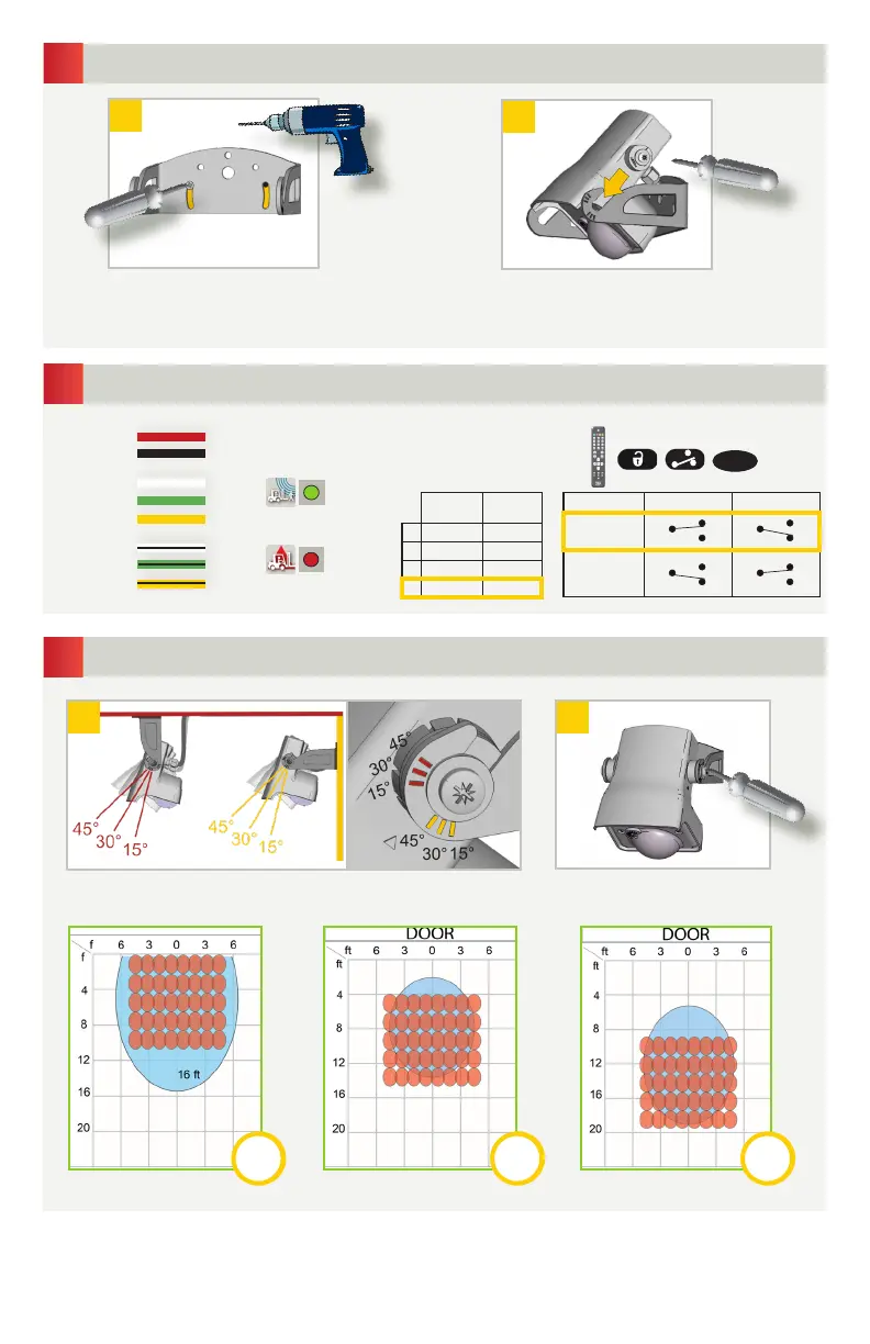
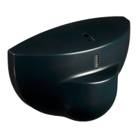
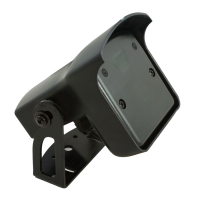
Position the sensor on the bracket and
tighten the screws.
Remove the bracket from the sensor.
Drill 2 holes accordingly.
Secure the bracket.
MOUNTING
WIRING
SENSOR ANGLE
Adjust the angle of the sensor to position the detection fields.
Tighten the screws firmly.
RECOMMENDED
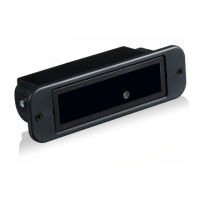
RADAR OUTPUT
Motion signal
AIR OUTPUT
Presence signal
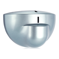
CEILING
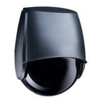
WALL
RED
BLACK
WHITE
GREEN
YELLOW
WHITE/BLACK
GREEN/BLACK
YELLOW/BLACK
Motion
Relay
Presence
Relay
1 Active Passive
2 Passive Active
3 Passive Passive
4 Active Active
Description Detection No Detection
Active
Relay
COM COM
Passive
Relay
COM COM
NO
NC
NO
NC
NO
NC
NO
NC
RELAY CONFIGURATION
COM
NO
NC
COM
NO
NC
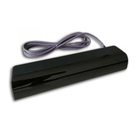
• The graphics above are not to scale and are for illustration purposes only. These graphics represent approximate detection fields when
mounted at 16 feet high. AIR-Infrared field = emitting spots detectable by using the SPOTFINDER. The actual detection field is slightly
smaller and is influenced by external factors.
• It’s important to adjust the sensor angle to position the detection fields correctly for your application. Utilizing a mounting bracket,
sensor location, and reveal will dictate the sensor angle for your application.