2
7
8
6
1
3
5
4
1
2
DESCRIPTION SPECIFICATION
SENSOR TILT ANGLE 15° to 45°
SUPPLY VOLTAGE
12 to 24VAC ±10%
12 to 24VDC +30% / -5%
MAIN FREQUENCY 50 to 60Hz
POWER CONSUMPTION < 3.5W
RELAY OUTPUT
- Max. Voltage
- Max. Current
- Max Switching Power
2 Relays with switch-over contact (voltage free)
60 VDC / 125 VAC
1A (resistive)
30W (DC) / 60VA (AC)
INSTALLATION HEIGHT
IS40: 8 ft - 16 ft (2.5 - 6 m)
IS40XL: 6.5 ft - 11.5 ft (2 - 3.5 m)
TEMPERATURE RANGE -22°F ( -30°C) to + 140°F (60°C)
PROTECTION DEGREE IP65 / NEMA 4
NORM CONFORMITY Electromagnetic compatibility (EMC) according to 2004/108/EEC, R&TTE: 1999/5/EC
DIMENSIONS (D X W X H) 5 in. X 4 in. X 3.75 in. (127mm x 102mm x 96mm)
MATERIAL
- Housing
- Face
ABS
Polycarbonate
COLOR
- Housing
- Face
Black
Transparent Purple
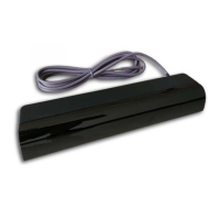
CABLE LENGTH 32 feet (10m)
TECHNOLOGY MICROWAVE DOPPLER RADAR INFRARED
RADIATED FREQUENCY 24.175 GHz 875 nm
RADIATED POWER DENSITY < 5 mW/cm² < 250mW/m²
DETECTION MODE Motion Presence
MAXIMUM DETECTION FIELD
IS40: 13 ft x 16 ft (4m x 5m)
IS40XL: 13 ft x 6.5 ft (4m x 2m)
IS40: 10 ft x 10 ft (3m x 3m)
IS40XL: 7.5 ft x 7.5 ft (2.3m x 2.3m)
OUTPUT HOLD TIME 0.5 sec. to 9 sec. 0.5 sec.
REACTION TIME 100ms 250ms
MINIMUM TARGET SPEED 2 in/sec (5cm/sec) in sensor axis 0 in/sec (0cm/sec)
LED SIGNAL Green = Activation Relay Red = Presence Relay
RADAR ANGLE / SENSOR ANGLE -8° to 22° (relative to sensor front face) 15°, 30°, 45°
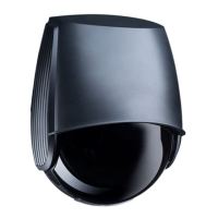
IS40 / IS40XL
USER’S GUIDE
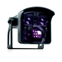
COMBINED ACTIVE INFRARED (IR) AND MICROWAVE SENSOR
75.5695.01 EN 20120113 Page 1 of 9
IS40 / IS40XL
- The IS40 uses
Microwave technology
for motion detection
and Active Infrared
technology for
presence detection.
SPECIFICATIONS
IS40: for normal to high mounting 8 ft - 16 ft (2.5 - 6 m)
IS40 XL: for low mounting 6.5 ft - 11.5 ft (2 - 3.5 m)
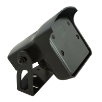
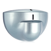
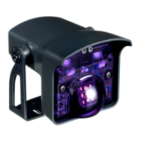
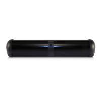
1. IR angle indicator
2. LED’s
3. IR emitters
4. Radar angle adjustment
dial
5. Radar detection antenna
6. Sensor angle adjustment
7. Bracket
8. Cable
DESCRIPTION