21
To perform a shock pulse measurement, follow these steps:
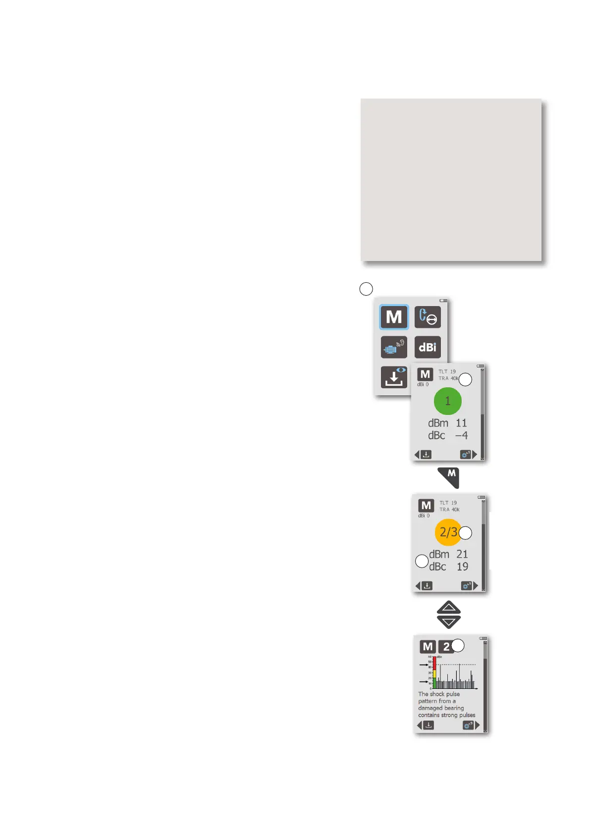
1. In the Main display (A), select the Measure icon and
press ENTER.
Before taking a measurement, make sure that the shaft
diameter and rotational speed of the bearing, or its
dBi, have been entered (se chapter “Input data”), or
the reading will be incorrect. The Measurement display
opens, showing the most recent reading (B).
2. For a new measurement, press the probe tip (or connect
the external transducer) to the measuring point, then
briefly press the MEASURE key. A single blue pixel briefly
appears at the bottom of the display, indicating that a
measurement cycle is in progress. The display backlight
is then turned off until the measurement is completed.
When the display lights up again, it shows two measure-
ment results (C): the maximum value, dBm, and the carpet
value, dBc. Depending on the dBm value, the display shows
a green, yellow or red condition indicator.
When an external transducer is used, the instrument dis-
plays a TLT warning sign if the transducer line test result is
unsatisfactory. The TLT value for the current reading is shown
at the top of the display, along with the probe/transducer
type used:
TRA INT PROBE = internal probe
TRA EXT PROBE = external probe
TRA 40K = 40000 type transducer
TRA 42K = 42000 type transducer
For further information about TLT, please see chapter “Trans-
ducer Line Test”.
3. When measurement is completed, the condition indicator
(D) shows the evaluated bearing condition (for normal-
ized readings). Press the DOWN arrow key to scroll down
to the evaluation code (E). This code (between 1 and 6)
refers to the Evaluation Flowchart on pages 34-35, which
must be used to further evaluate bearing condition.
When the instrument shows high readings (yellow or red
condition indicator), immediately verify their nature and
probable cause. Do not conclude that there is bearing dam-
age without further investigation. As first measures:
• use the headphones to identify the shock pulse pat-
tern; for more information, see chapter “Listening to
the shock pulse pattern”
• measure on and outside of the bearing housing to
identify the shock pulse source.
4. To scroll back up to the measuring result, press the UP
arrow key.
To return to the Main display from the Measurement display,
press the BACK key.
Shock pulse measurement
Check:
- Shaft diameter and rpm, dBi set-
ting
- Measuring point in the load zone
- Probe pointed straight at the
bearing
- Adapter (transducer) properly
mounted
- Adapter surface clean, undamaged
- Quick connect transducer firmly
attached
Main display
A
C
E
Measure
Scroll up/down
Condition indicators:
Red: bad (≥35)
Yellow: caution (21–34)
Green: good (≤ 20)
D
B
 Loading...