13
The following two pages show measuring points and possible
adapter or transducer installations. How to install measuring
equipment is described in the SPM installation manual.
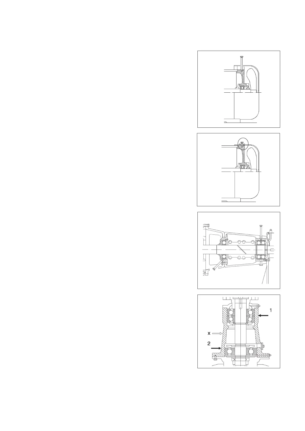
Through hole for long adapter
Figure A shows how a measuring point beneath a fan cover
can be reached with a long adapter, through a hole in the
cover.
Adapter with lock nut
In figure B, the fan cover is fastened directly to the motor
shield, which is also the bearing housing. One of the cover’s
holding screws can be replaced by an adapter with lock nut.
Bearing housings beneath brackets
Consult machine drawings and identify the bearing housing
before selecting a measuring point.
In figure C, showing a pump, the bearings are placed in two
separate housings inside the bearing bracket.
The bearing pair at measuring point 1 can be reached with
a long adapter through a clearance hole in the bracket. The
hole must be large enough to allow bearing adjustment and
still prevent metallic contact between bracket and adapter.
Measuring point 2, placed below and opposite to the pump
outlet (load direction!) can be reached with a long adapter
through an opening in the pump shield.
Multiple bearings in one housing
If there are several bearings in the same housing, they are
normally treated as a single bearing. Figure D shows the
bearing arrangement for a vertical pump. It is not possible
to distinguish between the shock pulses from the paired
bearings in point 1.
There is also a risk for cross talk between point 1 and point
2, which means that the shock pulses from the bearing in
worst condition are picked up at both points. Check signal
strength with the probe. Use one measuring point only if
readings are identical in both points. This point (x) can be
placed halfway between points 1 and 2.
A
Measuring points, examples
1
2
C
B
D
 Loading...