Commissioning
C6920 29Version: 3.2
1 2 3
4
5
6
7
8
Battery
24 V
Power
24 V DC
+UPS
+ +
PC_ON
Power-Status
-
-
X2
X1
X1 X2
ext. switch
N0 N0
0 V 22-30 V DC
UPS Output
L max = 10 m
1,5 mm / AWG14
2
1
2
GND
+24 V
PTC
24 V/3,4 Ah
30 V/9 A
C9900-U330 battery pack
-
+
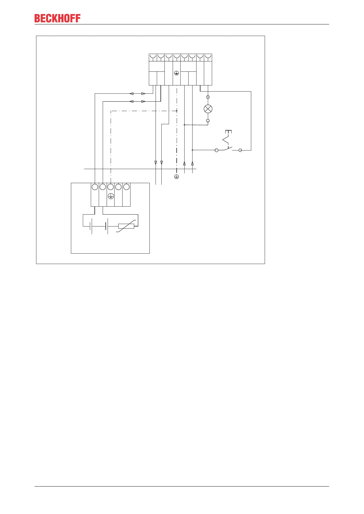
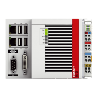
Fig.18: C6920_Wiring diagram
So that the Industrial PC still has a monitor output in case of a power failure, a Control Panel can be
connected to the UPS output of the power supply unit. Even after a power failure there is a voltage of 24 V
DC
between the UPS output and the negative pole of the battery pack. The maximum load is 1.4 A (max. 2.5 A
from year of manufacture 2016).
Once the PC has been de-energized via the UPS software, the UPS output is switched to 0 V. A connected
panel is switched off.