Do you have a question about the Beckhoff CB3064 Series and is the answer not in the manual?
Information on using the documentation and adhering to national standards.
Safety instructions, symbols, FCC approvals, and essential safety measures for operators.
Description of the manual's scope and applicability to the product.
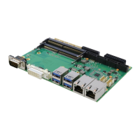
Highlights the main capabilities and components of the CB3064 motherboard.
Provides a structured list of all hardware features and their specifications.
Lists technical specifications and recommended documents for detailed information.
Covers power supply connectors, voltage, and optional SUPS module functionality.
Details the supported CPUs and memory module specifications for the motherboard.
Visual overview of connector locations on the CB3064 motherboard.
Details the 2x10-pin power input connector and pinout.
Describes the SO-DIMM260 memory sockets and their pin assignments.
Pinout and specifications for the DVI-D connector.
Details the 30-pin connector for video and USB 3.0 interfaces.
Describes standard USB 3.0 connectors for channels 1-4.
Details internal USB 2.0 connectors (2x8-pin and 2x4-pin).
Describes the two Gigabit Ethernet LAN interfaces and their pinouts.
Details the four SATA interfaces, their connectors, and capabilities.
Describes the 9-pin DSUB serial COM1 connector and RS232 signals.
Details the 2x40-pin custom connector for PCI-Express devices.
Describes the 2x6-pin connector for General Purpose Input/Output.
Details the 2x5-pin connectors for external fans and monitoring signals.
Describes the 2x12-pin connector for system control signals, power button, and LEDs.
Details the tricolor RGB LED, its colors, intervals, and meanings.
Guidelines for navigating and using the BIOS setup utility.
Displays key system information like board revision, BIOS version, and processor details.
Settings for CPU type, speed, caches, virtualization, and power management.
Configure Intel LAN connections and network stack options.
Settings for trusted computing, BIOS security, and Intel AMT management.
Configure PCI Express clock gating, latency timers, and decoding.
Settings for USB module version, legacy support, and device configuration.
Settings for SATA controllers, RAID, and NVMe devices.
Diagram showing the location and dimensions of mounting holes on the PCB.
Detailed pin 1 dimensions for various connectors and components on the PCB.
Diagrams for DIE center, cooling area, and overall PCB dimensions.
Details power supply requirements and electric power consumption of the board.
Specifies operating, storage, and thermal conditions, including temperature and humidity limits.
Information on branch offices, support hotlines, service centers, and headquarters.
Lists used interrupts and details of PCI devices with their bus numbers and functions.
Lists reserved SMBus device addresses and their functions.
| Product Series | CB3064 |
|---|---|
| Manufacturer | Beckhoff |
| Category | Motherboard |
| Power Supply | 24 V DC |
| Ethernet | 2x Gigabit Ethernet |
| USB | USB 3.0/2.0 |
| Display Interfaces | 1x DVI-D |
| Expansion | Mini PCI Express slot |
| Operating Temperature | 0°C to +55°C |
| USB Ports | 4x USB 2.0, 2x USB 3.0 |