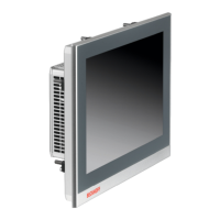
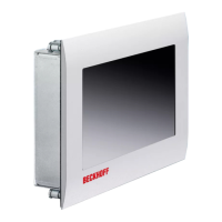
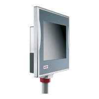
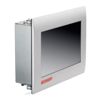
Product overview
CP27xx 13Version: 2.0
3.2 Interface description
In the basic configuration, the panel PC includes the following interfaces:
• DVI (X103)
• USB (X104 - X107)
• Ethernet RJ45 (X108, X109)
• Power supply (X110)
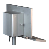
The interfaces are located on the rear side of the panel PC at the bottom in the connection section.
Fig.4: CP27xx_connection section
3.2.1 DVI
The panel PC is equipped with a DVI connector (X103) to which a DVI-capable monitor can be connected.
Only digital signals are transmitted.
Fig.5: CP27xx_DVI port pin numbering
Table3: DVI interface pin assignment
Pin Assignment Pin Assignment Pin Assignment
1 TDMS Data 2 - 9 TDMS Data 1 - 17 TDMS Data 0 -
2 TDMS Data 2 + 10 TDMS Data 1 + 18 TDMS Data 0 +
3 TDMS Data 2/4 Shield 11 TDMS Data 1/3 Shield 19 TDMS Data 0/5 Shield
4 not connected 12 not connected 20 not connected
5 not connected 13 not connected 21 not connected
6 DDC Clock 14 + 5 V Power 22 TDMS Clock Shield
7 DDC Data 15 Ground (+ 5 V, Analog H/
V Sync)
23 TDMS Clock +
8 Analog Vertical Sync 16 Hot Plug Detect 24 TDMA Clock -