List of figures
CP27xx50 Version: 2.0
List of figures
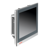
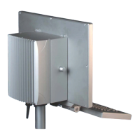
Fig. 1 CP27xx_without and with push button extension......................................................................... 10
Fig. 2 CP27xx_structure......................................................................................................................... 11
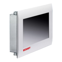
Fig. 3 CP27xx_structure stainless steel device...................................................................................... 12
Fig. 4 CP27xx_connection section......................................................................................................... 13
Fig. 5 CP27xx_DVI port pin numbering.................................................................................................. 13
Fig. 6 CP27xx_USB interface pin numbering......................................................................................... 14
Fig. 7 CP27xx_Ethernet interface pin numbering .................................................................................. 15
Fig. 8 CP27xx_voltage socket pin numbering........................................................................................ 16
Fig. 9 CP27xx_installation PCIe module................................................................................................ 17
Fig. 10 CP27xx_name plate..................................................................................................................... 18
Fig. 11 CP27xx_delivery state clamping lever ......................................................................................... 22
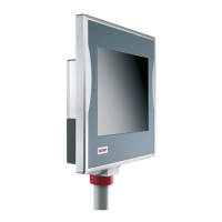
Fig. 12 CP27xx_wall positioning .............................................................................................................. 23
Fig. 13 CP27xx_control cabinet installation ............................................................................................. 23
Fig. 14 CP27xx_assembly of strain relief housing ................................................................................... 25
Fig. 15 CP27xx_disassembly of strain relief housing............................................................................... 26
Fig. 16 CP27xx_grounding bolt functional earthing ................................................................................. 27
Fig. 17 CP27xx_wiring diagram C9900-U330.......................................................................................... 29
Fig. 18 CP27xx_wiring diagram C9900-U332.......................................................................................... 30
Fig. 19 Beckhoff Device Manager - Change passwords .......................................................................... 33
Fig. 20 Beckhoff Device Manager – Start page ....................................................................................... 34
Fig. 21 Beckhoff Device Manager - Onboard EtherCAT P....................................................................... 35
Fig. 22 CP27xx_removal from the control cabinet ................................................................................... 37
Fig. 23 CP27xx_removal installation cutout ............................................................................................. 37
Fig. 24 CP27xx_Select "Cleaning Mode"................................................................................................. 39
Fig. 25 CP27xx_configuration "Cleaning Mode" ...................................................................................... 39
Fig. 26 CP27xx_access device components ........................................................................................... 41
Fig. 27 CP27xx_replacing the battery ...................................................................................................... 42
Fig. 28 CP27xx_exchange CFast ............................................................................................................ 44
Fig. 29 CP27xx Stainless steel front_replacement silicone deal.............................................................. 45