Product overview
CP27xx 15Version: 2.0
3.2.3 Ethernet RJ45
The panel PC has two Gigabit LAN ports (X108, X109). The 100Base-T and 1000Base-T Ethernet standards
enable the connection of corresponding network components and data rates of 100/1000 Mbit/s. The
required speed is selected automatically.
The RJ45 connection technology with twisted-pair cables is used. The maximum length of the cable
connection is 100m.
If you use the Ethernet ports with EtherCAT or for Real-Time Ethernet applications, you have to regard the
following distinction:
The Ethernet port (X109, LAN2) connected via PCIe with the i210 controller is generally suitable for cycle
times <= 1 ms and for distributed clock applications with EtherCAT.
The Ethernet port (X108, LAN1) integrated in the chipset with the i219 controller is generally suitable for
EtherCAT and Real-Time Ethernet applications with cycle times > 1 ms (without distributed clocks).
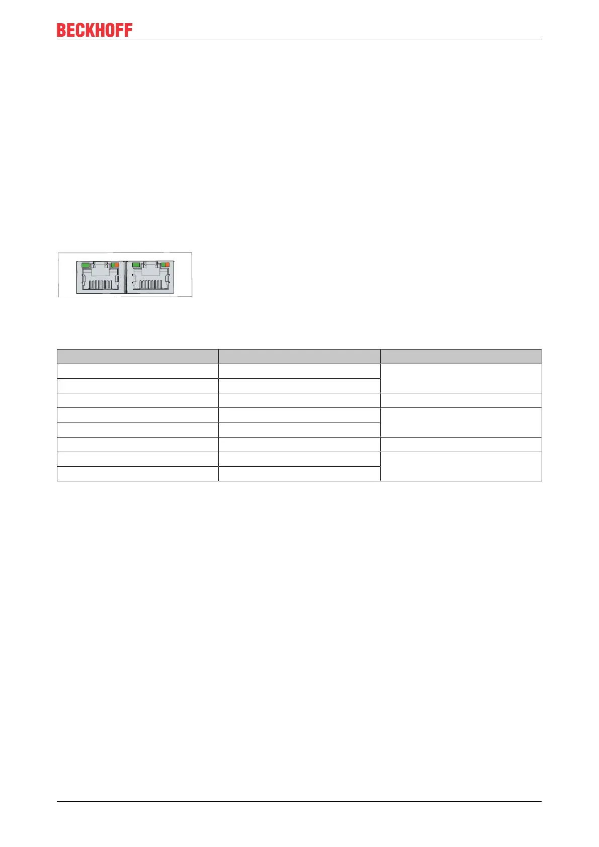
Fig.7: CP27xx_Ethernet interface pin numbering
Table6: Ethernet interface pin assignment
Pin Signal Description
1 T2 + Pair 2
2 T2 -
3 T3 + Pair 3
4 T1 + Pair 1
5 T1 -
6 T3 - Pair 3
7 T4 - Pair 4
8 T4 -
The LEDs of the LAN interfaces indicate the activity and the speed of the data transmission (Mbit/s). The
LED on the left in the figure indicates whether the interface is connected to a network. If this is the case, the
LED lights up green. The LED flashes when data transmission is in progress on the interface.
The LED on the right in the figure indicates the speed of the data transmission. If the speed is 100Mbit/s the
LED is orange, at 1000Mbit/s it is green.