Commissioning
CP27xx 29Version: 2.0
You can use the UPS output of the power supply unit and connect a Beckhoff Control Panel as a second
display. If the supply voltage fails and the panel PC is only supplied by the battery pack, the control panel
remains in operation. Second display operators can use it to read the power failure notification, back up data,
and shut down the operating system.
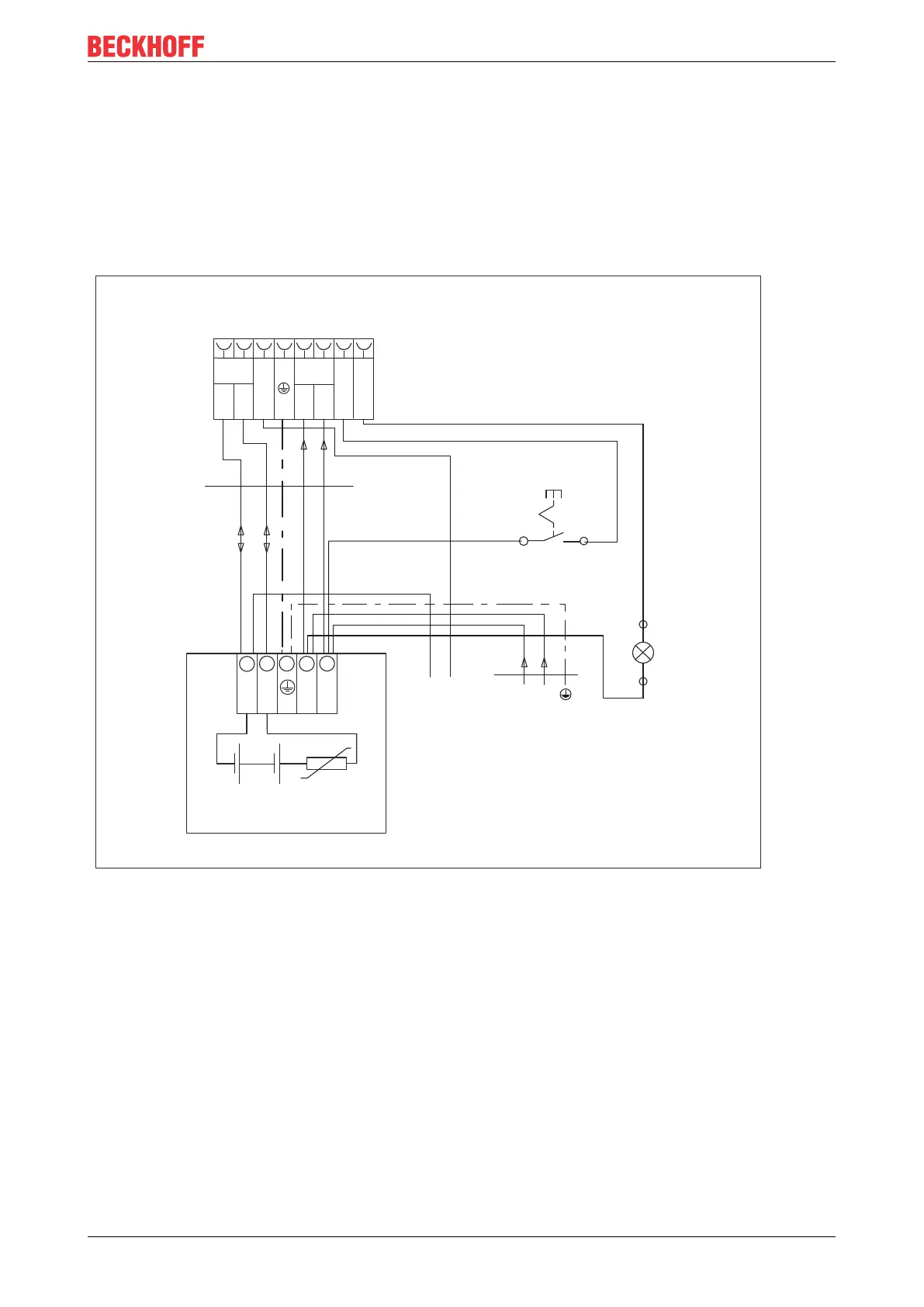
In the case of the C9900-U330 battery pack, PIN 4 and 5 of the battery pack are available for looping
through a 24V supply. Accordingly, you can connect a three-core sheathed cable with plus and minus of the
supply voltage as well as protective earth to the battery pack and then connect to the PC with a five-core
sheathed cable. The method of connecting different components can be taken from the wiring diagram in fig.
17.
1
2
GND
+24 V
PTC
24 V/3,4 Ah
30 V/9 A
C9900-U330 battery pack
3
4
5
1 2 3
4
5
6
7
8
Battery
24 V
Power
24 V DC
+UPS
+ +
PC_ON
Power status
-
-
Industrial PC power connector
L max = 10 m
1,5 mm / AWG14
2
0 V24 V DC
-
+
UPS Output
X1
X2
Power status
X1 X2
ext. switch
N0 N0
Fig.17: CP27xx_wiring diagram C9900-U330
In the case of the C9900-U332 battery pack, PIN 5 and 6 of the battery pack are available for looping
through a 24V supply. Accordingly, you can connect a three-core sheathed cable with plus and minus of the
supply voltage as well as protective earth to the battery pack and then connect to the PC with an 8-core
sheathed cable. The method of connecting different components can be taken from the wiring diagram in fig.
18.