3-2
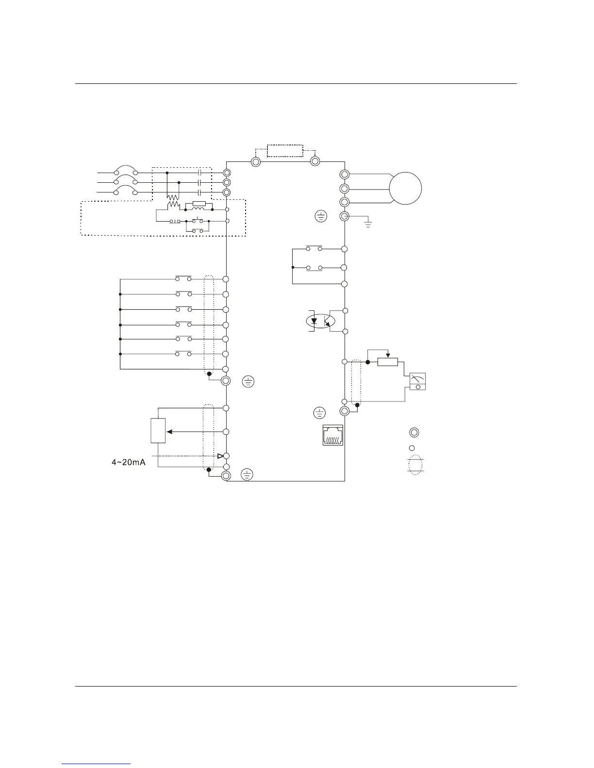
3.1 Basic Wiring Diagram
Users must connect wiring according to the following circuit diagram shown below.
B2
U/T1
V/T2
W/T3
IM
3~
MO1
MCM
RS-485
NOTE: Do not plug a Modem or telephone line to the RS-485 communication
port, permanent damage may result. Terminal 1& 2 are the power
sources for the optional copy keypad and should not be used while
using RS-485 communication.
6←1
B1
E
RA
RB
RC
120VAC/250VAC 5A
24VDC less than 2.5A
M0
M1
M2
M3
M4
M5
GND
AVI
GND
+10V 10mA(MAX)
3
2
1
VR
0
~
10VDC
VR
:
3K
~
5KΩ
FM
GND
+
-
VR(1KΩ)
DC 0
~
10V
RJ-11
1:15V
2:GND
3:SG-
4:SG+
5:Reserved
6:Reserved
Braking resistor (optional)
Main Circuit Power
The spec. of main circuit
terminal is M3.0
Factory default
Forward/Stop
Reverse/Stop
Reset
Multi-step 1
Multi-step 2
Multi-step 3
Common signal
Master Frequency setting
factory default is VR which is
on the digital keypad
Analog voltage
Analog current
Power for speed setting
series interface
AC Motor
Grounding
Multi-function indication
output contact
Factory default:
indicates malfunction
Multi-function Photocoupler
output contact 48VDC 50mA
Factory default: Indicates
during operation
Analog output
Factory default:
output frequency
For adjustment
Main circuit (power)
terminals
Control circuit terminals
Shielded leads
* If it is single phase model, please select any of the two input power
terminals in main circuit power.
* Single phase model can be input 3-phase power.
S/L2
T/L3
NFB
R/L1
S/L2
T/L3
SA
OFF
ON
MC
MC
RB
RC
Recommended Circuit
when power supply
is turned OFF by a
fault output
R/L1
ACI
E
E
E
B550 Series sensorless vector frequency drive