5-22
This parameter selects if the Output Frequency, Current, PID feedback or Output Power
will be the output signal on the AFM terminal (0 to 10V).
Pr.44
Analog Output Gain
a
Factory Setting: 100
Settings 00 to 200% Unit: 1%
This parameter sets the voltage range of the analog output signal on output terminal
AFM.
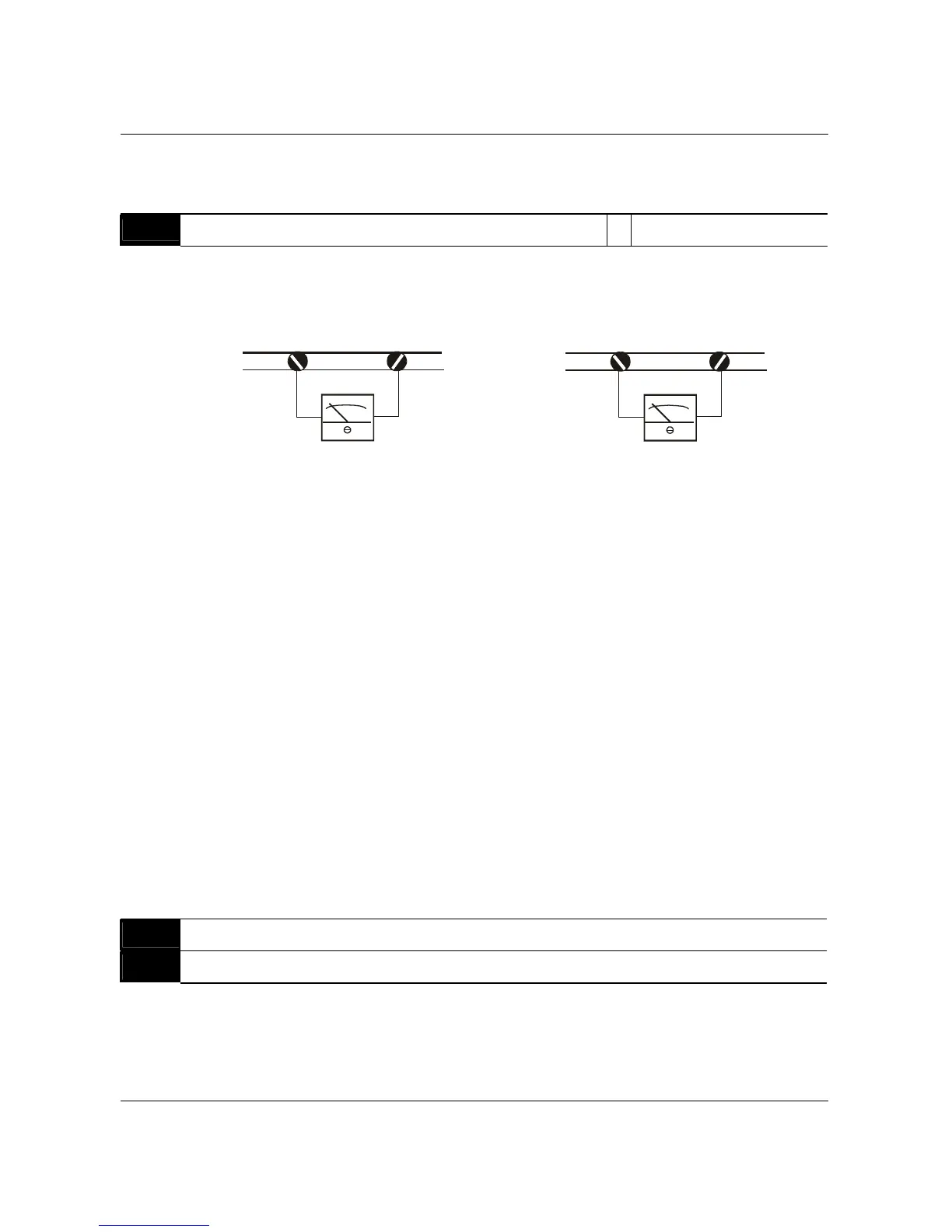
+-
AFM
GND
Analog Frequency Meter
+-
AFM
GND
Analog Current Meter
The analog output voltage is directly proportional to the output frequency of the AC drive. A
setting of 100% on Pr.44 makes the Maximum Output Frequency (Pr.03) of the AC drive to
correspond to the +10VDC analog voltage output. (The actual voltage is about +10VDC, and
can be adjusted by Pr.44)
The analog output voltage is also directly proportional to the output current of the AC drive. A
setting of 100% on Pr.44 makes the 2.5 times rated current of the AC drive to correspond to
the +10 VDC analog voltage output. (The actual voltage is about +10 VDC, and can be
adjusted by Pr.44)
Note: Any type of voltmeter can be used. If the meter reads full scale at a voltage less than 10
volts, then Pr.44 should be set by the following formula:
Pr.44 = ((meter full scale voltage)/10)×100%
For Example: When using a meter with a full scale of 5 volts, adjust Pr.44 to 50%
Pr.45
Multi-function Output Terminal 1 (Photocoupler output) Factory Setting: 00
Pr.46
Multi-function Output Terminal 2 (Relay output) Factory Setting: 07
Settings 00 to 24
B550 Series sensorless vector frequency drive