5-20
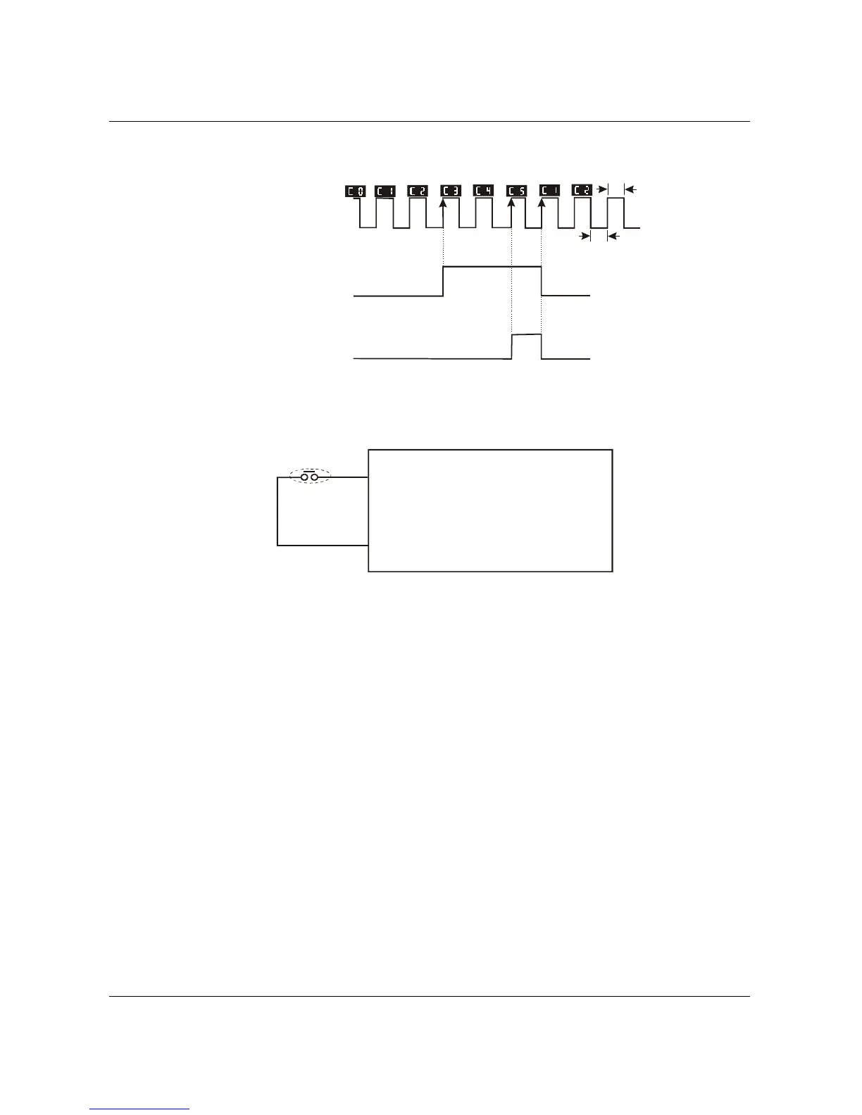
Note: The Counter Trigger input can be connected to an external Pulse Signal Generator when
counting a process step or unit of material. See the diagram below.
2ms
2ms
Indication value
(Pr.64=1)
Counter trigger signal
Multi-function input terminal
Signal output with Pr.97
counter value is attained.
(Pr.97=3)
(Pr.45/46=13)
Signal output with Pr.96
counter value is attained.
(Pr.96=5)
(Pr.45/46=14)
The trigger timing
can't be less than
2ms.(<250Hz)
(Pr.38 to Pr.42 =18)
19 Counter Reset:
Parameter value 19 programs Multi-Function Input Terminal: M1 (Pr.38), M2 (Pr.39), M3
(Pr.40), M4 (Pr.41) or M5 (Pr.42) to reset the counter.
GND
19 reset the
counter value.
Mx "close": reset counter.
Reset counter
20 Parameter Disable:
Enter value (20) to disable any Multi-Function Input Terminal: M1 (Pr.38), M2 (Pr.39), M3
(Pr.40), M4 (Pr.41) or M5 (Pr.42)
Note: Purpose of this function is to isolate unused Multi-Function Input Terminals. Any
unused terminals should be programmed to 20 to insure they have no effect on drive
operation.
22 Control Source: External Terminal / 23 Control Source: Keypad / 24 Control Source:
Communication:
Enter values 22, 23, or 24 to set the control source to be the external terminals, keypad or
communication respectively. This setting is used to create functions for manual/auto, and
remote/near-end control. When these three functions are used at the same time, the
priority is 22-I/O > 23-Keypad > 24-Communication.
B550 Series sensorless vector frequency drive