3-6
Terminal
Symbol
Terminal Function Factory Settings (NPN mode)
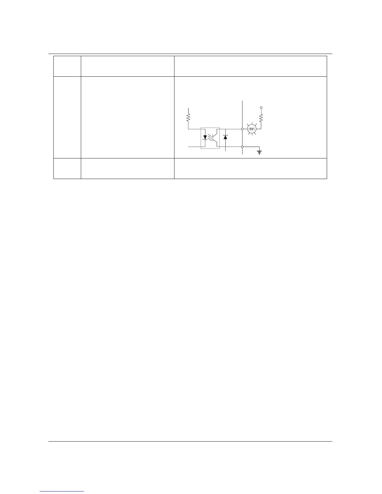
MO1
Multi-function Output Terminal
(Photocoupler)
Maximum: 48Vdc, 50mA
Refer to P45 for programming.
MO1-DCM
MO1
MCM
Internal Circuit
Max: 48Vdc/50mA
MCM
Multi-function Output Common
(Photocoupler)
Common for Multi-function Outputs
Note: Use twisted-shielded, twisted-pair or shielded-lead wires for the control signal wiring. It
is recommended to run all signal wiring in a separate steel conduit. The shield wire
should only be connected at the drive. Do not connect shield wire on both ends.
B550 Series sensorless vector frequency drive
 Loading...