GB Sound speed controller SFR-1
06.02.2019 BEIER-Electronic 11
If you want to disconnect the supply voltage of the SFR-1 from the battery,
always disconnect the positive lead of the battery first (or plus and minus at
the same time)! Never disconnect the negative lead first (or only)!
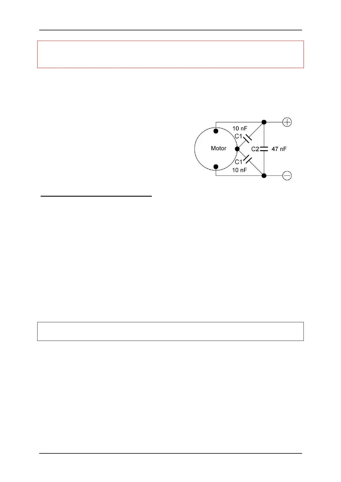
In case of poor or no interference suppression motors can be strong sources of
interference, which may interfere with the electronics of the SFR-1, especially the
sound output (whistling, buzzing in the speaker. Therefore motors should be
suppressed! With a 2.4 Ghz transmission and a
current motor, which is usually already
suppressed, disturbances are rare.
If you have problems with interferences, the
motor can be additionally suppressed with three
capacitors, as shown in the figure. The C1
capacitors are connected to the motor housing.
Connection of proportional inputs
To proportional inputs X2/1 - X2/6 up to 6 proportional channels can be connected
to the receiver. To proportional channels #1 and #2 there are already servo cabeles
soldered. For connecting the pin headers servo patch cables (15 and 30 cm) can be
ordered in our online shop.
Throttle channel X1 must be connected to the receiver in order to control the pace of
the speed contoller.
Steering channel X2 needs to be connected in case one of the folllowing functions
should be used:
• Activation of indicator lights by steering
• Automatic flashing of indicator lights while steering
• Steering inertia and steering angle limitation
• Transmission of steering signals to light module SM-IR-16-2 via infrared
The servo patch cables must be connected to the SFR-1 with the orange cable
pointing to the center of the board (down) and the brown cable to the edge (up).
 Loading...