54
Installation BRS20/22/30/32/40/42/50/52
Release
12
01/2022
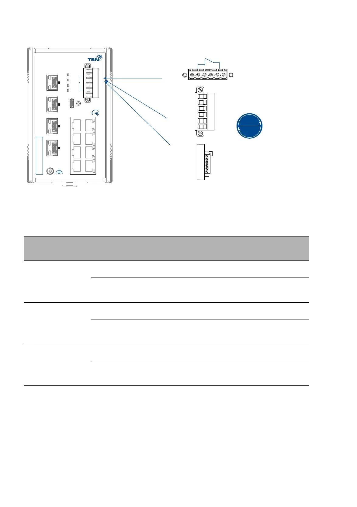
Supply voltage with characteristic value P
Figure 17: (1) DC voltage connection on the device, (2) terminal block mounted on
the device (front view), tightening torque, (3) terminal block mounted on
the device (view from above).
For the supply voltage to be connected, perform the following steps:
Remove the terminal connector from the device.
Connect the wires according to the pin assignment on the device with
the clamps.
Type of the voltages
that can be
connected
Specification of the supply
voltage
Pin assignment
When using PoE:
DC voltage
Rated voltage DC:
48 V DC
+ Plus terminal of the supply
voltage
Voltage range DC incl.
maximum tolerances:
46 V DC ... 57 V DC
- Minus terminal of the supply
voltage
When using PoE+: Rated voltage DC:
54 V DC
+ Plus terminal of the supply
voltage
Voltage range DC incl.
maximum tolerances:
52 V DC ... 57 V DC
- Minus terminal of the supply
voltage
Without using PoE or
PoE+:
DC voltage
Rated voltage range DC:
24 V DC ... 48 V DC
+ Plus terminal of the supply
voltage
Voltage range DC incl.
maximum tolerances:
19 V DC ... 60 V DC
- Minus terminal of the supply
voltage
Table 10: Supply voltage with characteristic value P: type and specification of the
supply voltage, pin assignment
ACA
PoE
Status
Power
1
2
3
4
IP-ADDRESS
2.5 GE
2.5 GE
GE
2.5 GE
2.5 GE
5
7
6
8
9
10
11
12
USB
z
P
0V 0V+54V(P2) +54V(P1)
RELAY
z
x y
+54 V(P1) +54 V(P2)
0 V 0 V
1
2
3
4.4 lb-in
0.5 Nm
RELAY