Operation
48
EDS309x_D00012_03_M_XXEN/11.2014
– Pay attention to identical directions of flow on the two measuring clamps (see connection
diagram). For this purpose the measuring clamps are marked with an arrow
Place the two measuring clamps successively and systematically around all parallel outgoing cables
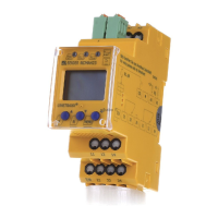
for loads. Outgoing cables for loads with an insulation fault are indicated by the flashing alarm LED
on the EDS195P. The alarm messages are output in the same way as for an application with a single
measuring clamp. For possible error messages see page 44.
Abb. 6.2: Insulation fault location in diode-decoupled DC systems (connection diagram)
PSA3052
MESSZANGE / CLAM
P
ON PROBE
Datenblatt / Da
t
asheet :
TGH13xx
Durchmesser / Diameter : 52 mm
Art.-N
r
. / Art.-no. : B 980 xxx
PSA3052
MESSZANGE / CLAM
P ON PROBE
Datenblatt / Dat
asheet :
TGH13xx
Durchmesser / Diameter : 52 mm
Art.-Nr. / Art.-no. : B 980 xx
PSA3052
MESSZANGE / CLAM
P ON PROBE
Datenblatt / Da
tasheet :
TGH13xx
Durchmesser / Diameter : 52 mm
Art.-N
r
. /
Art.-no. : B 980 6xx
PGH186
100mA
10 mA
25 mA
Imax
ON
ON
Us
L1(+)
L2(-)
L3
AC/DC
L-
L+
L+
L-
PGH185
S1
Selector switch
EDS/IMD
DC main distribution (DC 20-360 V)
Central coupling
of the insulation monitoring device (IMD)
and the locating current injector PGH185
Us AC 230 V
PSA3052/3020
PSA3052/3020
EDS195P
DC sub distribution
l
max.
= 10 m
l
m
a
x
.
=
1
0
m
L+
L-
Load
Insulation fault
Load
EDS195P
PSA3052/3020
PE
EDS195P
ISOSCAN®
I
L
I
n
ALARM
I n
I
L
INFO
MENU
HOLD
RESET
ESC
OK
EDS195P
ISOSCAN®
I
L
I
n
ALARM
I n
I
L
INFO
MENU
HOLD
RESET
ESC
OK
 Loading...


