4 iso685-x_D00022_12_Q_INTE/12.2023
ISOMETER® iso685…
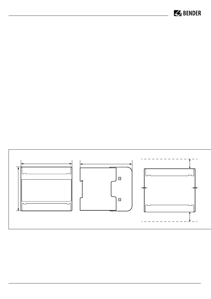
0 mm
20 mm
20 mm
108 110
93
Safety instructions
I
Danger! Electric shock! The terminals carry high
voltage and direct contact with these terminals
will likely result in electrocution. If the terminals
L1/+, L2, L3/- of the device are connected to a live
IT system, the terminals E and KE must not be dis-
connected from the protective conductor (PE).
I
Caution! Damage to property due to incorrect in-
stallation! Connecting more than one insulation
monitoring device may result in damage to the
installation. In addition, the device will not func-
tion and will not report an insulation fault if more
than one insulation monitoring device is connected.
I
Caution! Disconnect from the IT system! The insu-
lation monitoring device must be disconnected from
the IT system before insulation or voltage tests at the
installation and must remain so for the duration of
the test. Otherwise the device may be damaged.
Mounting
DIN rail mounting
Snap all mounting clips delivered with the device onto
the DIN rail in such a way that a safe and tight fit is ensured.
Sicherheitshinweise
I
gefahr! Elektrischer Schlag! An den Klemmen
liegt eine hohe Spannung an, die bei direkter
Berührung lebensgefährlich ist. Ist das Gerät mit
den Klemmen L1/+, L2, L3/- an ein betriebsbe-
dingt spannungsführendes IT-System ange-
schlossen, dürfen die Klemmen KE und E nicht
vom Schutzleiter (PE) getrennt werden.
I
VorsiCht! Sachschaden durch unsachgemäße
Installation! Die Anlage kann Schaden nehmen,
wenn Sie mehr als ein Isolationsüberwachungs-
gerät anschließen. Sind mehrere Geräte ange-
schlossen, funktioniert das Gerät nicht und meldet
keine Isolationsfehler.
I
VorsiCht! Trennung vom IT-System! Bei Isolations-
und Spannungsprüfungen an der Anlage muss
das Isolationsüberwachungsgerät für die Dauer
der Prüfung vom IT-System getrennt sein. Andern-
falls kann das Gerät Schaden nehmen.
Montage
Maße / Dimensions / Dimensions / Dimensiones Abstände / Distances / Disatances / Espaciones
Montage auf Hutschiene
Rasten Sie alle mitgelieferten Montageclips des Geräts
auf der Hutschiene unten so ein, dass ein sicherer und
fester Sitz gewährleistet ist.

 Loading...


