6 iso685-x_D00022_12_Q_INTE/12.2023
ISOMETER® iso685…
Screw mounting
Install the accompanying mounting clips manually or
by means of a tool in a way that they protrude beyond
the enclosure. Fix the device by means of three M4
screws.
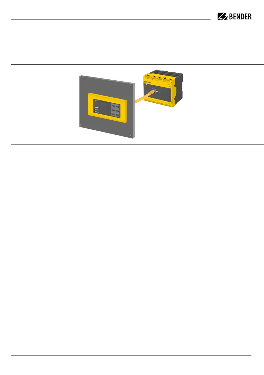
Sensor variants
Device version iso685(W)-S-x features neither a display
nor operating controls. It can only be used in combina-
tion with the FP200(W) and is operated via this front
panel.
Connection
Wire up the device according to the wiring diagram
taking account of the technical data. After connecting
the device, install the enclosed upper and lower termi-
nal cover!
I
Warning! Injury, fire and damage to property due
to a short circuit! When coupling the terminals
L1/+, L2, L3/- to the IT system ≤ 690 V to be mon-
itored, devices for protection against a short-
circuit can be omitted according to IEC 60364-4-
43:2008 or DIN VDE 0100430 if the wiring is car-
ried out in such a way as to reduce the risk of a
short-circuit to a minimum. Pay attention to
short-circuit proof and earth-fault proof wiring.
i
For UL applications:
Use 60/75 °C copper wires only!
For UL and CSA applications, the supply voltage
must be protected via 5 A fuses.
Schraubmontage
Bringen Sie die mitgelieferten Montageclips manuell
oder mittels Werkzeug in eine über das Gehäuse hinaus
ragende Rastposition. Befestigen Sie das Gerät mit drei
M4-Schrauben.
Sensor Varianten
Die Geräteausführung iso685(W)-S-x enthält kein Dis-
play und keine Bedieneinheit. Sie ist nur in Kombination
mit dem FP200(W) einsetzbar und wird über dieses in-
direkt bedient.
Anschluss
Verdrahten Sie das Gerät gemäß Anschlussplan. Beach-
ten Sie dabei die technischen Daten. Montieren Sie nach
dem Anschluss die obere und die untere mitgelieferte
Klemmenabdeckung!
I
Warnung! Verletzungen, Brände und Sach-
schäden durch Kurzchluss! Entsprechend DIN VDE
0100-430 können Sie auf Einrichtungen zum
Schutz bei Kurzschluss für die Ankopplung der
Klemmen L1/+, L2, L3/- an das zu überwachende
IT-System verzichten, wenn die Leitung oder das
Kabel so ausgeführt ist, dass die Kurzschlussgefahr
auf ein Mindestmaß beschränkt ist. Achten Sie auf
kurz- und erdschlussfeste Verlegung.
i
Für UL-Anwendungen:
Nur 60/75 °C Kupfer drähte verwenden!
Bei UL- und CSA-Anwendungen muss die Versor-
gungs spannung über 5 A-Sicherungen abgesichert
werden.

 Loading...


