Installation and connection
20
RCMB300-series_D00372_01_M_XXEN/06.2019
4.4 Connecting the device
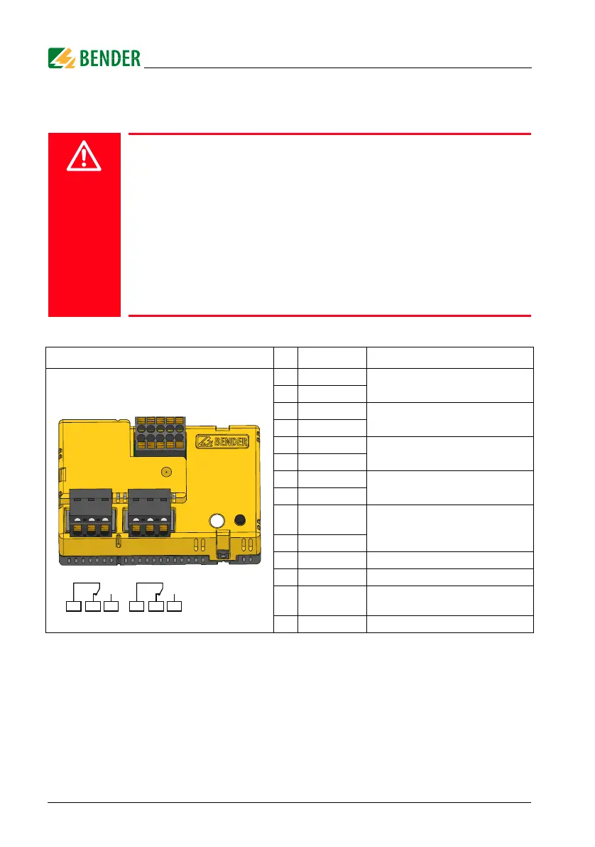
4.4.1 Device view RCMB30…
Tab. 4.1: Device view RCMB30…
Risk of electrocution due to electric shock!
Touching live parts of the system carries the risk of:
• An electric shock
• Damage to the electrical installation
• Destruction of the device
Before installing and connecting the device, make sure that the
installation has been de-energised. Observe the rules for working on
electrical installations.
Refer to the rated and supply voltage values as specified in the
technical data!
No. Terminal Meaning
1
24 V
Supply voltage U
S
2
GND
3
-
Not used
4
-
5
T/R
Connection external test/reset
6
GND
7
A
RS-485 interface
8
B
9
X1
Terminals for cable bridge for connection of
the integrated terminating resistor of the RS-
485 interface
10
X2
11
11, 12, 14 Relay K1 (prewarning)
12
21, 22, 24 Relay K2 (alarm)
13
–
Combined LED (Refer to "System states: LED
and output relays" on page 49.)
14
– Test and reset button "T"
21 22 2411 12 14
K1 K2
34789
125610
11 12
11 12
13 14
 Loading...