System states: LED and output relays
49
RCMB300-series_D00372_01_M_XXEN/06.2019
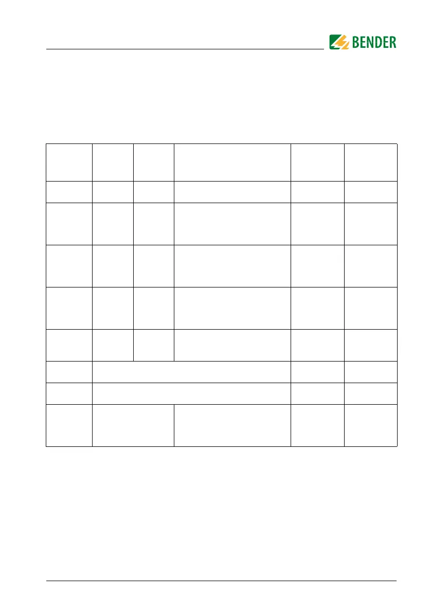
8. System states: LED and output relays
The LED indicates the system state by means of colours and lighting/flashing. The N/O
contacts of relay outputs K1 and K2 have defined switching positions for each system
state.
Tab. 8.1: System states: LED and output relays
System
state
GREEN
LED
ON
RED
LED
Alarm
Notes
Changeover
contact
K1
Changeover
contact
K2
Device
switched off
Off Off
Device is de-energised, no monitoring, no
monitoring function
De-energised De-energised
Normal operat-
ing state
Lights Off
The device is supplied with the specified
voltage and monitors the primary circuit.
No residual current flows which would lead
to tripping.
Energised Energised
Prewarning Lights Flashes briefly
The device is supplied with the specified
voltage and monitors the primary circuit.
A fault current flows which exceeds the set
limit of the prewarning.
De-energised Energised
Alarm state Off Lights
The device is supplied with the specified
voltage and monitors the primary circuit.
A fault current flows which exceeds the set
limit of the alarm.
De-energised De-energised
Device error Off Flashes slowly
The device is supplied with the specified
voltage and monitors the primary circuit.
An error is detected by the periodic self tests.
De-energised De-energised
Device in cali-
bration mode
Offset calibration procedure: see Page 27 De-energised De-energised
Device in
address mode
For procedure, refer to Page 25
Device signalling Flash quickly in alternation
Use Modbus register 20006 = 2
to detect the device in its environment
faster. Is automatically deactivated after one
minute.

 Loading...