21
STEP 7
( Sheave Installation )
1. Inspect Cables to ensure proper lengths. All Cables
should have ID tags showing proper Cable lengths.
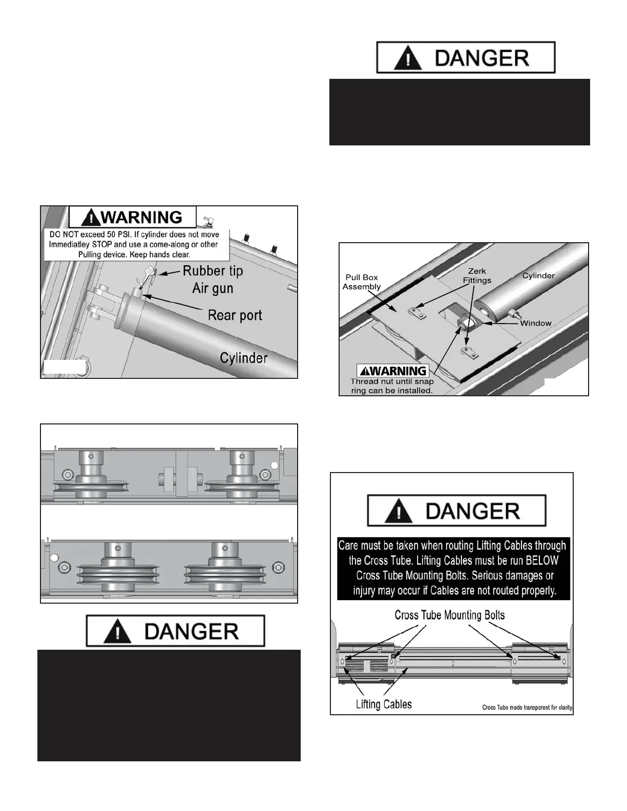
2. In order to install the Cables it is necessary to rst
extend the Hydraulic Cylinder. Remove both Cylinder port
plugs then use a rubber tipped air gun or come-along to
extend the Cylinder. (See Fig. 7.1)
IMPORTANT! - Be careful not to damage the chrome rod
during this step.
3. You must reinstall the Sheaves and Pins in the same
order as they were removed. (See Fig. 7.2)
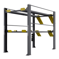
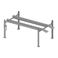
STEP 8
( Cable Installation )
1. Make sure the Pull Box Assy. with the window for the
retaining nut and Zerk ttings are facing down.
(See Fig. 8.1)
2. Route the threaded Cable ends through the ends of
each Cross Tube. Care must be taken when routing the
Lifting Cables to ensure they are routed below the Cross
Tube Mounting Bolts. (See Fig 8.2)
3. Route Cables over the Slack Safety Sheaves then to
the top of each Column. Secure using the M18 Hex Head
Nuts and Flat Washers. (See Fig. 8.3)
DANGER!
Failure to route Lifting Cables as described may lead to
serious personal injury and/or death to operator or by-
stander and/or may cause damage to property.
Fig 7.1
Fig 7.2
Fig 8.1
Fig 8.2
DANGER !
DO NOT PROCEED unless visual conrmation
is made of ALL Safety Locks. ALL locks MUST
be engaged before proceeding. Failure to com-
ply with these instructions may result in severe
personal injury or death. (See page 13)