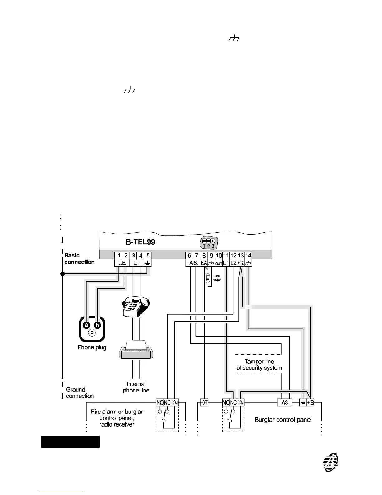
In the first case (dialler difficult to reach) connect a button or pulse lock be-
tween terminal 8[B.A.] and terminal 9[ ] as illustrated in figure 5. In the
second case (to stop alarm cycle/s when the Burglar system is disarmed),
terminal 8[B.A.] can be connected to terminal [+ON] of the Burglar system
(a terminal with Negative when the system is armed), or to terminal [+OFF]
of the Burglar system (a terminal with Positive when the system is dis-
armed). In the latter case, a 1k5, 1/4 W resistance between terminal [B.A.]
and [ ].
Figure 5 Basic and auxiliary connections.
14 Telephone dialler B-TEL99