33Bentone
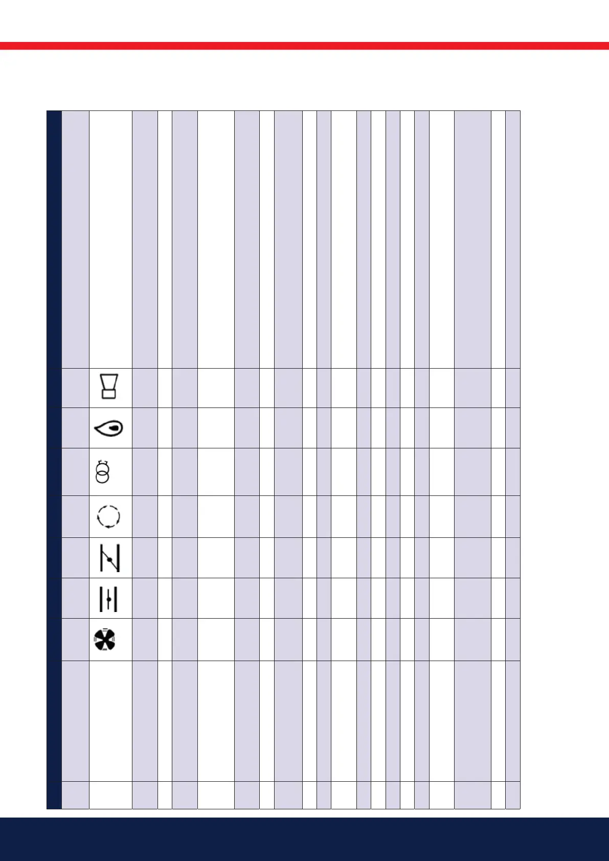
10.4 BurnerPro LED fault/lock code table
NO. FAULT LED 1 LED 2 LED 3 LED 4 LED 5 LED 6 LED 7 POSSIBLE SOLUTION
OPERATION LED = ON
Fan Open
damper
Closed
damper
Auto Ignition Flame Status
ICON
1 DIAGNOSTIC ERROR, MAIN MCU
INLET
RED Initial diagnostic error. Ensure correct status of inputs and outputs when the unit is
turned on.
2 LOCAL RESET
RED User-initiated manual reset/lockout or defective reset switch.
3 AIR SENSOR
RED Air sensor signal [connection 14] could not be detected by the end of the safety
time, or loss of the air sensor signal during burner operation
4 DIAGNOSTIC ERROR
RED “The system detected voltage at terminal 16, 17, 18, or 19 at the incorrect time, or
no voltage detected when necessary. Check cabling and makes sure the system is
running on a single line phase (50/60Hz)”
5 IONISATION FLAME LOSS
RED Flame loss. Inspect the system, check the gas pressure, ame detector, cabling,
etc.
6 IONISATION CIRCUIT FAULT
RED Replace the control unit. Contact reseller/distributor.
7 INTERNAL COMMUNICATION
ERROR
RED Reset the system to continue normal operation. Contact reseller/distributor if the
fault persists.
8 REMOTE RESET
RED The user has pressed Remote Reset or the remote controller has short-circuited.
9 IONISATION FAULT
RED Replace the control unit. Contact reseller/distributor.
10 MAIN PROGRAM SEQUENCE
ERROR
RED Replace the control unit. Contact reseller/distributor.
11 RAM TEST
RED Replace the control unit. Contact reseller/distributor.
12 PROGRAM SEQUENCE ERROR
RED Replace the control unit. Contact reseller/distributor.
13 READING ERROR INPUT
RED Check cabling and makes sure the system is running on a single phase (50/60Hz)
14 TIMER2 ERROR
RED Replace the control unit. Contact reseller/distributor.
15 CPU TEST FAILED
RED Replace the control unit. Contact reseller/distributor.
16 FLAME LOSS
RED Visually inspect the ame detector and con rm that the pilot light was lit
during start-up. Check the fuel supply system.
17 CABLE FAULT
RED The system detected voltage at terminal 16, 17, 18, or 19 at the incorrect time, or
no voltage detected when necessary. Check cabling and makes sure the system is
running on a single phase (50/60Hz)
18 SAFETY RELAY FAULT
RED Replace the control unit. Contact reseller/distributor
19 FUEL VALVE OPEN
RED Check fuel valve cabling. The valves may not be fully closed.