9 Bentone
d
1
d
2
d
3
2.4 Nozzle selection
See under Technical data: Recommended nozzle and nozzle table in order to
select the appropriate nozzle
2.5 Setting of brake disc and air flow
Once the different output modes have been selected prior to commissioning,
basic settings for the burner can be made as shown in the air damper and
brake disc diagrams. See under Default settings. Note that it is simply a
matter of a default setting that should be adjusted retrospectively once the
burner has started. You should then conduct a flue gas analysis and soot
quantity measurement.
2.6 Burner installation
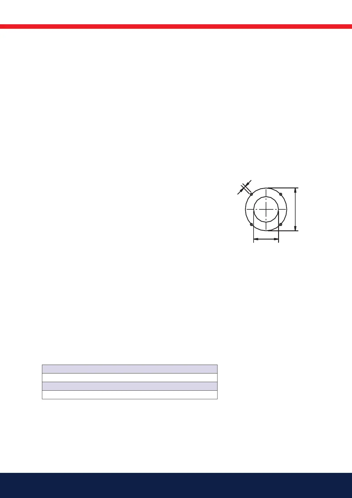
2.6.1 Hole pattern
Make sure the hole pattern on the boiler is designed for burner flange.
Combustion
device
d
1
d
2
d
3
B 70-3 (205) 225 M14 (310) 324-390
d1* If the burner tube is installed from inside the boiler
d
3
* The hole pattern can be moved down if the burner
tube is installed from the front and the tabs in the
flange are removed.
2.7 Recommended nozzle and
pressure
Because of the various boiler types with varying furnace geometries and
furnace loads, it is impossible to commit to a certain scattering angle or a
specific distribution pattern.
It should be noted that the scattering angle and distribution pattern changes
with pump pressure.
Nozzle: 45° Solid/semisolid
60° Solid/semisolid
80° Solid/semisolid
Pump pressure 14 bar (12-16 bar) depending on pump model