19
172 435 99 08-01
ELECTRIC EQUIPMENT
2(2)
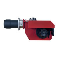
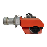
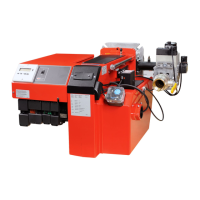
List of components LMG22 (BG550/BG550LN/BG650) Modulating with R316
A1 Gas burner control S8 Air pressure switch
A3 Valve, leak tester, S11 Change-over switch, Aut.-man.
Dungs VPS 504 S12 Change-over switch, Increase-
A6 Power control R316 Reduce
A6(2) PT 100-sensor, S20 Main switch 1-phase
Thermocouple, current/voltage T1 Ignition transformer
B1 Ionization electrode X1 Connection terminal board
F1 Operation fuse X2 Earth terminal
F2 Operation fuse X3 Plug-in contact, burner
F3 Operation fuse X4 Plug-in contact, boiler
F4 Operating fuse 1A X7 Plug-in contact, 3-phase,
H1 Operating lamp burner
K1 Motor contactor with thermal X8 Plug-in contact, 3-phase,
overload protector boiler
M1 Burner motor X9 Plug-in contact, power
M2 Damper motor, controller R316, burner
L&S SQN75.624.A21B X10 Plug-in contact, power
S1 Operating switch controller R316
S3 Control thermostat S9 Gas pressure switch
S4 Temperature limiter Y1 Gas solenoid valve 1
S5 Micro switch for hinged door Y3 Safety solenoid valve
S7 Main switch 3-phase
Mains connection and fuse in accordance with local regulations.
Function LMG22
1.Operating switch ON-Thermostat ON-Gas pressure switch ON-Air
damper closed.
A control is made that the air pressure switch does not indicate fan pressure.
Then the burner motor starts.
2.Air damper motor opens.
The air damper motor opens the damper to max. position. A control is made
that the air pressure switch indicates sufficient fan pressure.
3.Air damper motor closes.
The air damper motor closes to min. load position. Then the ignition spark
is formed.
4.Main and safety valves open
The gas is ignited. The ionization electrode indicates a flame.
5.The safety time expires.
The ignition spark goes out. The safety time expires. If there is no flame or
if for some reason the flame disappears after this time limit, the burner control
locks out.
6.Operating position.
The burner is in operating position and can now change over to the capacity
controlled by the regulator.
7.Stop.
The operation of the burner can now be interrupted by means of the operating
switch or the thermostat.
The control locks out. The red lamp in the control is lit. Restart the burner by pressing the reset
button.