50
172 305 25 05-01
1(3)
GENERAL INSTRUCTION
Flame monitoring and measurement of ionisation current
The burner is monitored according to the ionisation principle. Check the
ionisation current on start-up and on each service call.
The reason for a low ionisation current may be leaking currents, bad
connection to earth, dirt or a faulty position of the flame electrode in the
burner head. Sometimes also a faulty gas/air mixture may cause too weak
a ionisation current.
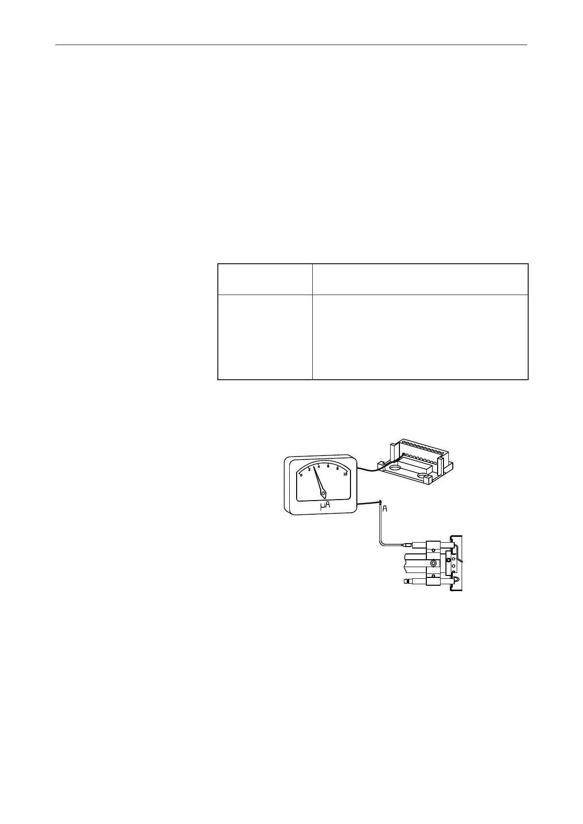
The ionisation current is measured by means of a microampere meter
(μA) connected in series with the flame electrode and the gas burner
control.
Connect the μA-meter, see figure. Min. required ionisation current according
to table. In practice this current must be considerably higher, preferably
more than 10 μA. All the gas burners are equipped with a ionisation cable
that can be slit which facilitates the connection of the μA-device.
Flame monitoring
Gas control Connection to terminal Min. ionisation
in gas control current required
LMG Serie A 1 2 μ A
LMG Serie B 2 10 μA
LGB 1 10 μ A
LFL 24 10 μ A
MMI 810 2 5 μ A
TMG 740-3 1 5 μ A