23 Bentone BFG 1
D
M
6.3 Startup
After the burner has been mounted on the boiler and the electrical connection,
de-aeration and tightness control have been performed, the burner is ready to
start-up.
Read the sections dealing with gas valve and pressure switch settings before
start-up.
Open the ball valve and turn on the main switch, start the burner and begin
setting up the system.
6.4 Control of combustion
Check combustion using ue gas analysis instruments. Set the burner to about
20% excess air and check that good combustion is obtained. Check the actual
gas ow on the gas meter to ensure that the correct input power is achieved.
Recommended air excess at basic setting
Gas quality
Excess air ue gases% O
2
Natural gas
4 ±1
Propane
Butane
Liqueed petroleum gas
Biogas
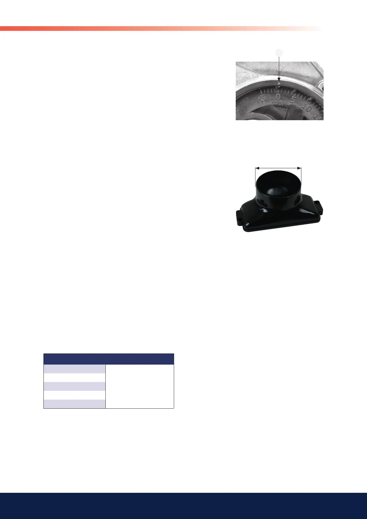
6.2.2 Inlet cone, air control
The air ow is also affected by the position of the intake cone. This rarely needs
adjustment, however, and should be maintained in the standard position
”STD” for good operation and starts. (A cast-in arrow on the fan housing
indicates the position of the inlet cone. In addition to the scale on the inlet
cone casting, there is also a mark (M) indicating the factory setting.
6.2.3 Rotation of air intake
The air intake can be rotated into various positions, in order to t the burner
into different environments.
To rotate the air intake, loosen the three screws securing the air intake and the
two screws fastening the air pressure switch. Then rotate the air intake to the
desired position and tighten the screws.
The air intake position does somewhat affect the air ow through the burner.
The position giving the largest ow is with the air intake downwards.
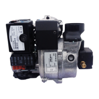
6.2.4 Air duct
A hose connection via a air duct is available in three different dimensions, 48,
68 and 78 mm outer diameter ”D”. The air duct is installed on the air intake at
the place where the grid is installed in the standard design.