Do you have a question about the Berchtold CHROMOPHARE D 650plus and is the answer not in the manual?
Overview of CHROMOPHARE® D generation, components, and unique features.
Manufacturer details, manual usage, accessory guidelines, and literature.
BERCHTOLD's responsibility and procedures for inspecting equipment upon receipt.
Equipment compliance with EC/UL guidelines and annual servicing recommendation.
Use of CHROMOPHARE® light as medical lighting for local illumination in treatment rooms.
Crucial safety precautions for operating the CHROMOPHARE® light.
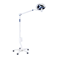
Requirements for mounting and installing CHROMOPHARE® lights by authorized personnel.
Procedures for initial start-up checks of the CHROMOPHARE® light.
Methods for cleaning, disinfecting, and sterilizing CHROMOPHARE® lights and handles.
Diagrams and parts lists for various CHROMOPHARE® models.
Instructions for operating control units and adjusting light functions.
Methods for adjusting light field size using hand grips or LFN models.
Procedure for removing and replacing the sterilizable hand grip.
List of available accessories, options, and system variants.
Procedure and safety notes for replacing halogen bulbs.
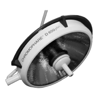
Detailed technical specifications, dimensions, and certifications for the D 650plus model.
Technical specifications, dimensions, and certifications for D 530plus and D 500plus models.
Technical specifications, dimensions, and certifications for the D 650 model.
Technical specifications, dimensions, and certifications for D 530 and D 500 models.
How to identify the serial number and its components on the type plate.
Comprehensive lists of spare parts with part numbers for various models.
Procedures for transformer mounting and adjustment for different models.
Visual descriptions and part numbers for key components.
Detailed test points, diagrams, and voltage specifications for troubleshooting.
Procedures to adjust the weight compensation on the spring arm.
How to adjust the spring arm's height movement for optimal positioning.
Tools and procedures for adjusting brake screws on various joints for mobility control.
Checklist for routine maintenance of CHROMOPHARE® lights.
Wiring diagrams for D 650plus/D 650 models with various configurations.
Wiring diagrams for D 530plus/500plus/530/500 models with various configurations.
Wiring diagrams for D 650plus/650 models with multiple light heads.
Wiring diagrams for mixed model combinations.
Wiring diagrams for specific model configurations.
Wiring diagram for OR-lights integrated with a camera system.
List of fuse values to be installed on-site for different light models.
Required terminal voltages for the CHROMOPHARE® light or Power Box.
| Illuminance | 160, 000 lux |
|---|---|
| Light source | LED |
| Cooling | Passive |
| Power Supply | 100-240 V AC, 50/60 Hz |
| Color rendering index (CRI) | 96 |
| Dimming | Yes |