Berges electronic • D–51709 Marienheide-Rodt • Tel. 02264/17-0 • Fax 02264/17126
Operating manual 21.12.98
ACP 3000 — 0.37–15.0 04_GB
28
VIN1 Analog speed input 1. Selectable through jumper J20 for 0–5 VDC, 0–10 VDC, or 0/4–20 mA DC. A 4 mA
offset is programmed by
24-FSEL
. Only VIN1 is active with functions 0–4. If a function between 4 and 7
selected, the reference value is the sum of the two analog inputs or, if
24-FSEL
has been programmed
accordingly (page 38), it is the difference between VIN1 and VIN2 (functions 8–11). Functions 12–15
switch between VIN1 and VIN2. VIN1/VIN2 changeover via PS3.
VIN2 Analog speed input 2. Selectable through jumper J20 for 0–5 VDC or 0–10 VDC. Only VIN1 is active with
functions 0–4. If a function between 4 and 7 selected, the reference value is the sum of the two analog in-
puts or, if
24-FSEL
has been programmed accordingly (page 38), it is the difference between VIN1 and
VIN2 (functions 8–11). Functions 12–15 switch between VIN1 and VIN2. VIN1/VIN2 changeover via PS3.
REF 5.2 VDC reference voltage, 3 mA maximum load. USE ONLY FOR A FREQUENCY CONTROL POTEN-
TIOMETER (5 kΩ recommend).
FWD Digital input for Forward operation. May be programmed for maintained (standard) or momentary contacts
by
21-MODE
. See page 36.
REV Digital input for Reverse operation. May be programmed for maintained (standard) or momentary contacts
by
21-MODE
. See page 36.
V+ Positive nominal 12 VDC voltage. Only for use with digital inputs (see pages 59 to 61). NO OTHER USE IS
ALLOWED.
MOL Motor Overload relay input. May be configured to generate a fault on opening or closing. May also be con-
figured to command a Coast-to-Stop on opening or closing. See page 47,
77-MOL
.
PS1
PS2
PS3
Digital inputs normally used for preset speed selection. Jumper J20 selects pull-up or pull-down logic (see
page 29). PS3 can be defined as a Run/Jog selector or VIN1/VIN2 switch by
21-MODE
(see page 36), or
as the ART selector by
41-RSEL
(see page 39), unless the PI Regulator is enabled and PS3 is used as an
ON/OFF switch. Eight preset speeds are available if all 3 inputs are used, and four are available if PS3 is
redefined via
21-MODE
or
41-RSEL
.
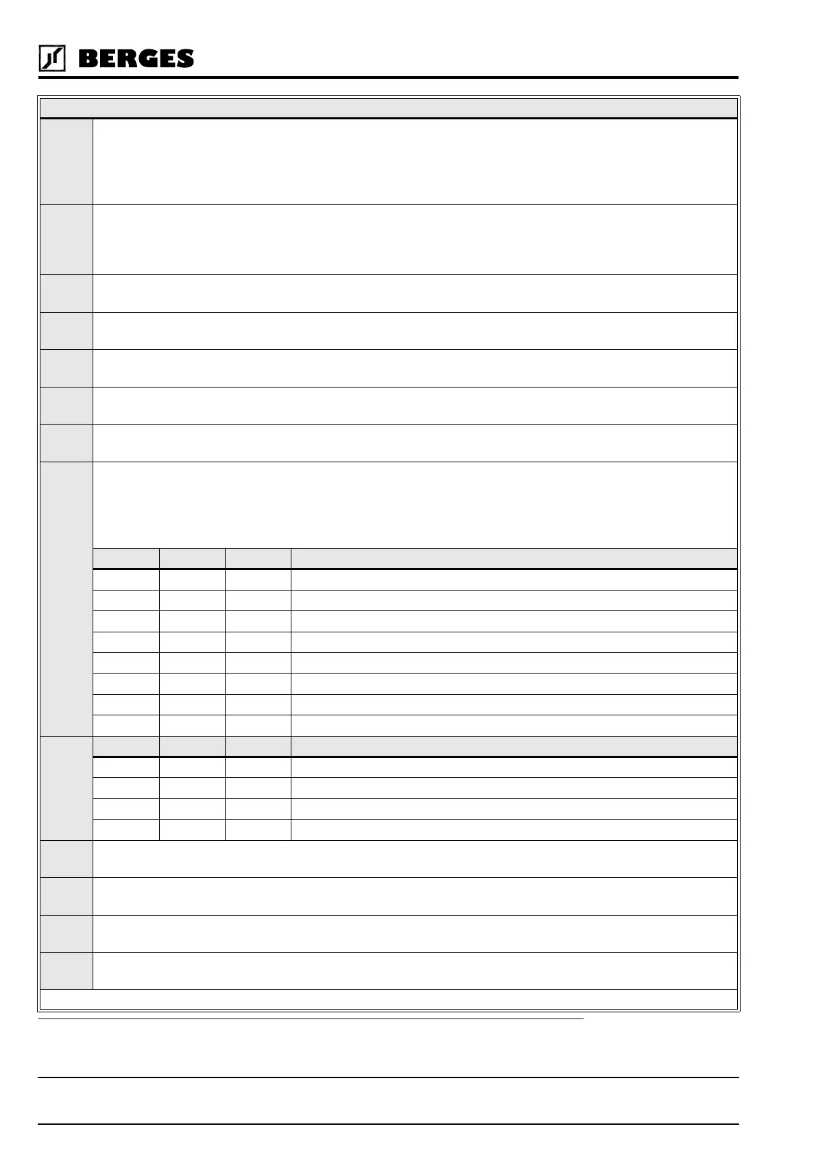
PS1 PS2 PS3 Effective Speed Reference
0 0 0 Basic speed setpoint (keypad or terminals)
100 33-F2
010 34-F3
110 35-F4
001 36-F5
101 37-F6
011 38-F7
111 32-FMAX
PS1
PS2
(1)
PS1 PS2 PS3 Effective Speed Reference
0 0 N/A Basic speed setpoint (keypad or terminals)
10N/A 33-F2
01N/A 34-F3
11N/A 35-F4
ST1 Digital output (open collector transistor). May be set to activate under one of ten conditions. See
72-ST1
(page 46). Maximal load: 24 VDC, 50 mA.
NO Normally open contact for the Auxiliary Relay. Will close when the relay is activated. Rating is 115/240 VAC
at 1 Ampere.
RCM Auxiliary relay common terminal. May release by appropriate adjustment at one of ten preset conditions.
See page 46,
75-STR
.
NC Normally closed contact for the Auxiliary Relay. Will open when the relay is activated. Rating is 115/240
VAC at 1 Ampere.
Table 3.3
(1) These settings will be utilized when PS3 is redefined via parameter
21-MODE
or
41-RSEL
, or when the PI Regulator is enabled and
PS3 is used as an ON/OFF switch.
DESCRIPTION OF TERMINALS