English
7
6 TRAVEL LIMIT SETTINGS
The actuator is factory-set for a 90°travel.
It features 2 devices to limit the travel:
• Cams trigger switches to switch off power at an end position or
to signal a position.
• Mechanical stops mechanically block rotation to protect the valve
in case of over-travel. They must not be used as travel limits.
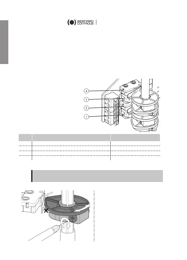
Setting a single cam
The cam rotates as the
output shaft and triggers a
switch by pushing on its
lever.
Cams orientation are factory
pre-set, yet you can still re-
adjust them upon the
installation if necessary.
Rep. Function Status before installation
Counter-clockwise travel limit
Counter-clockwise signalling
How to adjust a single cam
At the desired position of the actuator output:
1) Turn the setting screw of
the corresponding cam
Phillips-head screwdriver.
The cam disk is then turning.
2) Set the cam disk until you
hear a click from the
switch. It
triggering of the switch.
Make sure the cams contact the switch according to their proper
direction of travel, otherwise you could damage the switch.
8