10
3.3.2 Installing the cable glands
AT actuators are fitted with 2×M16 and 3×M20 cable entries.
How to install the cable glands
For each cable entry used
1. Remove the plug from the cable
entry with a 19 mm (M16 entry) or
23 mm (M20 entry) open-end
wrench.
2. Separate the sealing nut from its
cable gland.
3. Screw and tighten the cable gland
into the cable entry.
4. Insert the sealing nut on the cable
and pass the cable through the cable gland.
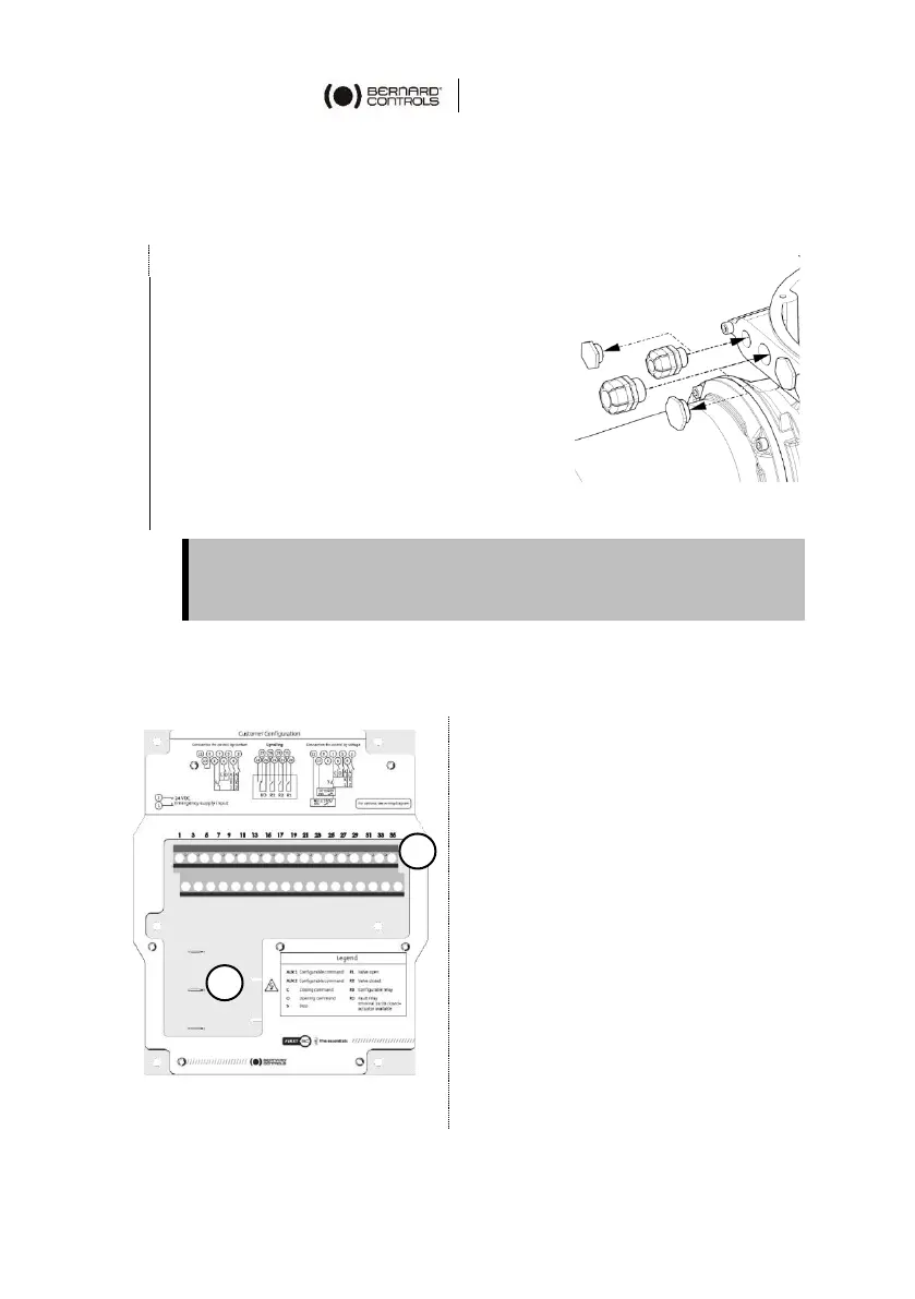
3.3.3 Wiring power and control cables
Terminal board
On a side of the electronics
assembly there are:
• a screw terminal block to
connect command and
signaling (A).
• 3 push-on connectors to
connect the power supply
(B).
Control terminals: 1-36
Power connectors (3Ph/1Ph)
• 3Ph: L1, L2, L3 with phase
correction
• 1Ph: L (Live), N (Neutral)
Unused entries must be kept closed using plugs as they are part of
the components allowing the actuator to be rated with IP68
protection.