EasyManuals Logo

Bernard Controls AT LOGIC v2 User Manual

Bernard Controls AT LOGIC v2
72 pages
To Next Page IconTo Next Page
To Previous Page IconTo Previous Page
Page #20 background imageLoading...
Page #20 background image
English
20
4.5 Remote controls
The AT LOGIC remote control system can be operated using an
external or internal voltage supply.
The input circuits are fully opto-isolated. The pulse command system
requires 4 connecting wires on the client terminal strip: Common,
STOP, OPEN, CLOSE. If the STOP local command button is not used,
do not connect the STOP wire. The OPEN (or CLOSE) contact must be
maintained to operate the actuator.
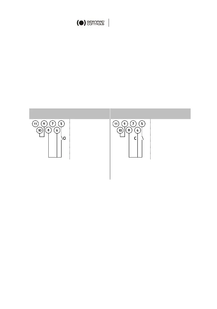
4.5.1 Single switch control (Dry Contact)
The actuator can be controlled via a single external switch.
Opening
Closing
O: Open
C: Close
Switch closed: valve opens
Switch open: valve closes
Switch closed: valve closes
Switch open: valve opens
The actuator must be configured for the priority type
required (open or close), see §5.5.3.

Questions and Answers:

Question and Answer IconNeed help?

Do you have a question about the Bernard Controls AT LOGIC v2 and is the answer not in the manual?

Bernard Controls AT LOGIC v2 Specifications

General IconGeneral
BrandBernard Controls
ModelAT LOGIC v2
CategoryRanges
LanguageEnglish