15
4 ACTUATOR CONTROLS
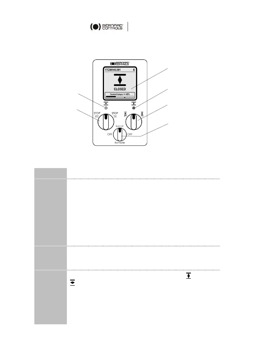
4.1 Control panel
The AT LOGIC control panel consists of a screen, 2 control knobs, 1
control selection knob and 2 configurable LEDs.
The screen displays operating status or LOGIC menu
The control selection knob allows to choose the one of the
following control modes:
• Local: the actuator is controlled using this Control
panel, or with a Smartphone via Bluetooth®
• Remote: the actuator is controlled remotely
• OFF: the controls are deactivated
The actuator is set to Local at startup.
The control mode can be locked with an optional padlock
at the bottom of the control panel.
The knobs are used for operation (upper function) or
menu navigation (lower function). Once released, these
knobs return to the center position.
The LEDs indicate the actuator status (CLOSED or OPEN
).
Default colors are red for CLOSED and green for OPEN.
They can be set according to the country’s standard (see
§5.4.4).
One LED will blink during operation according to the travel
direction, and both during Bluetooth® connection.
Open / close &
navigation knob
Control mode
selection knob