5.1 USE A QUALIFIED ELECTRICIAN
5.1.1 In the event of any motor not starting / magnets not working, the following
procedure should be adopted.
5.1.2 Check voltage at control box at PWR Plug to Control PCB in the electrical drawer.
5.1.3 Check main fuses/breakers feeding machine if voltage is not normal - also check
individually labelled fuses on Control PCB.
5.1.4 Check that EMERGENCY STOP BUTTON on control pendant is not locked in
STOP position.
5.1.5 Check for open circuit on overload terminals 95 and 96, press overload reset
button to correct (see Service Bulletin #4).
5.1.6 Check that reset button on clear control box lid is not permanently in contact with
red button on overload. Adjust as required (see Service Bulletin #1).
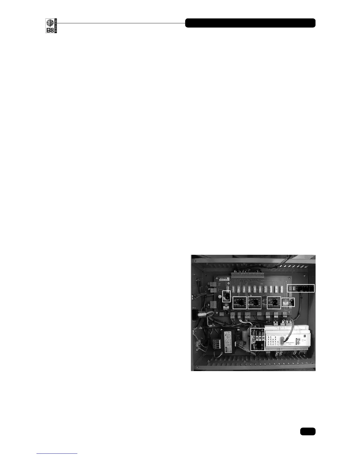
5.1.7 Listen for the functioning of all four contactors/relays in the control box by
operating the individual motor control buttons, and the reversing microswitch.
Contactor number 4 should move in and out depending on the position of the
microswitch.
The contactors are positioned as shown:
1. Coolant Relay
2. Grinding Motor Contactor
3. Traverse Contactor
4. Traverse Reversing Contactor
5. Magnet Relay
6. Overload (beneath reset button)
PWR: Power Plug
5.1.8 If the relevant contactor appears to be operating correctly check the voltage on the
out going plug at the Control PCB and then the voltage at the appropriate motor
terminals.
5. Electrical Fault Finding
5
1
6
4
3
2
PWR
16
ANGLEMASTER • AM3000
© Bernhard and Company Limited