BestCode Next Series 8 Technical Manual October 2022 Page 193 of 290
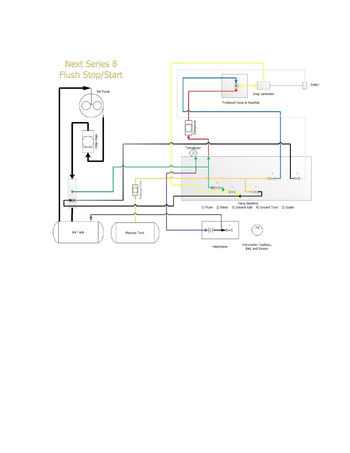
Flush Start / Stop and Printhead Clean Function Flow
This flush diagram is used to show how the stop and start cleaning process is achieved.
Flush Flow Logic: Active Valves: Gutter, Flush, Solvent Tank
1) Printhead Valve turns off.
2) The Bleed Valve opens to apply Vacuum to the drop generator.
3) Once the jet has stopped, the Solvent Tank Valve opens
4) Solvent is pulled through the drop generator.
5) The Solvent Tank Valve and Bleed Valve de-activate.
6) The Flush Valve activates, and pushes clean solvent out of the drop generator into the gutter to clean the gutter
and gutter sensor.
7) The Flush Valve and Gutter Valve de-activate.