KC5000 Technical manual — Installation 9
A
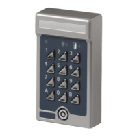
Connection between keypad M65 and the
central unit.
Suitable cable: 4 x 0,5 mm².
B
Connection of the electric lock.
Door opening relay. Voltage free contacts.
Maximum load over contacts 2A.
(----- = fail safe operation e.g. maglock).
C
Remote opening input. For connection of an
exit push button (push to make).
D
Connection of the telephone line. If remote
programming is required.
E
Ground.
Note! It is crucial that the central unit is
grounded, since it has built-in lightning
protection. This will not work unless the unit
is grounded.
F
Connection of the supplied 24V AC power
supply.
H
Background lighting on/off.
Set the link to OFF if the background lighting
should be permanently shut off.
I
For connection of remaining keypads,
(up to 6 doors).
Door 1: Terminal nos. 1 to 4.
Door 2: Terminal nos. 5 to 8.
Door 3: Terminal nos. 9 to 12.
Door 4: Terminal nos. 13 to 16.
Door 5: Terminal nos. 17 to 20.
Door 6: Terminal nos. 21 to 24.
The keypads are to be connected in the same
way as the first connected keypad.
In each keypad you then connect:
Terminal 1 to terminal no 5, 9, 13, 17 or 21.
Terminal 2 to terminal no 6, 10, 14, 18 or 22.
Terminal 3 to terminal no 7, 11, 15, 19 or 23.
Terminal 4 to terminal no 8, 12, 16, 20 or 24.
J
Printer connection.
Is also used when you connect a PC or a
modem (see separate manual for connection).