8 KC5000 Technical manual — Installation
Connecting the KC5000
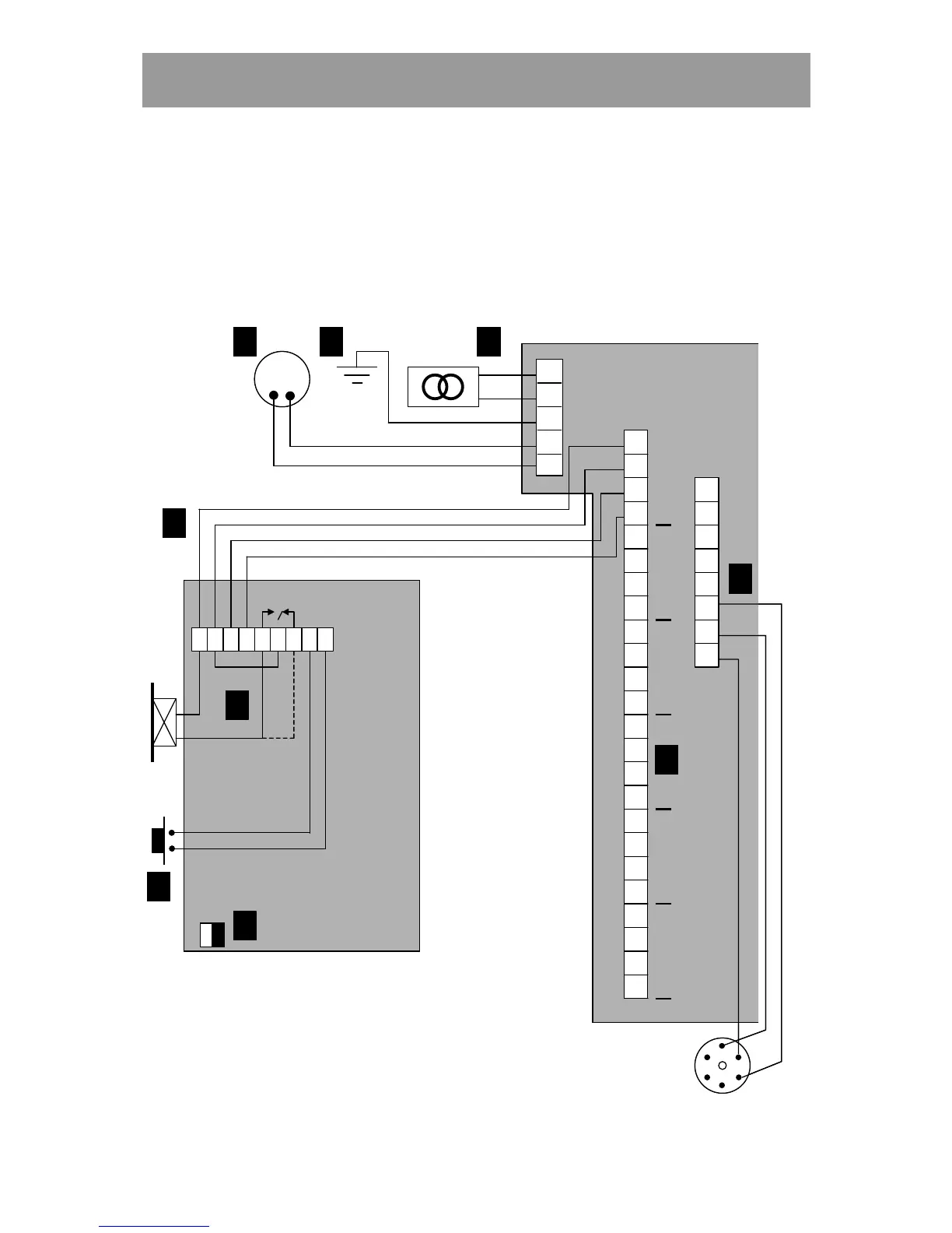
The diagram below shows how to connect the keypad to the central unit, the
electric lock and the exit request button, and also where the power supply,
telephone line and printer (if any) should be connected.
ON
OFF
M65
1
2
3
4
5
PL 1
LINE CARD
KC5000
1
2
3
4
5
6
7
8
9
10
11
12
13
14
15
16
17
18
19
20
21
22
23
24
PL 2
PL 3
1
2
3
4
5
6
7
8
1
2
3
4
5
6
A
B
C
D E F
H
I
J
1
2
3
4
5
6
Rx
Tx
DTR
0V
1 2 3 4 5 6 7 8 9
TELE
ON
OFF
ON
OFF
M65
1
2
3
4
5
PL 1
LINE CARD
KC5000
1
2
3
4
5
6
7
8
9
10
11
12
13
14
15
16
17
18
19
20
21
22
23
24
PL 2
PL 3
1
2
3
4
5
6
7
8
1
2
3
4
5
6
AA
BB
CC
DD EE FF
HH
II
JJ
1
2
3
4
5
6
Rx
Tx
DTR
0V
1 21 2 3 43 4 5 65 6 7 87 8 9
TELE