13
Installation, Operation and Maintenance Manual
MAN616_EAC Rev. 5 July 2020
Section 2: Installation
Installation
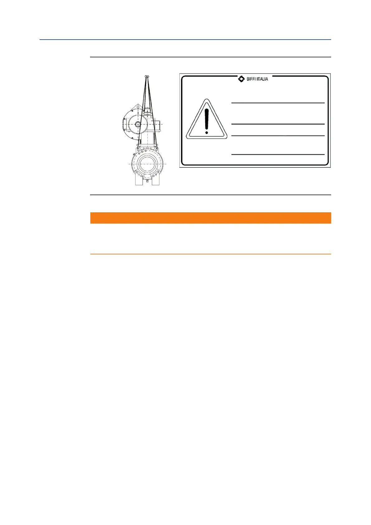
Figure 9 Lifting Points for ALGAS-QA
!
WARNING
Any lifting method different from what described above is strictly forbidden.
Bif reject any responsibility for damages to goods or injuries to persons coming from
wrong lifting operations.
The actuator can be assembled onto the valve ange either by using the actuator-housing
ange with threaded holes, or by the interposition of an adaptor ange or a spool piece.
The actuator drive sleeve is generally connected to the valve stem by an insert bush or a
stem extension.
The assembly position of the actuator, with reference to the valve, must comply with the
plant requirements (cylinder axis parallel or perpendicular to the pipeline axis).
To assemble the actuator onto the valve proceed as follows:
1. Check that the coupling dimensions of the valve ange and stem, or of the
relevant extension, meet the actuator coupling dimensions.
2. Bring the valve to the position related to the actuator spring operation.
3. Lubricate the valve stem with oil or grease in order to make the assembly easier.
Be careful not to pour any of it onto the ange.
4. Clean the valve ange and remove anything that might prevent a perfect
adherence to the actuator ange and especially all traces of grease, since the
torque is transmitted by friction.
5. If an insert bush or stem extension for the connection to the valve is supplied
separately, assemble it onto the valve stem and fasten it by tightening the proper
stop dowels.
6. Bring the actuator to the position caused by the spring operation.
Lifting lugs to be used for the
actuator only. Do not lift valve and
actuator together.
Do not disassemble top or bottom
cover spring loaded.
Porential electrostatic charge hazard.
Bif is not liable for any personel
injury due to incorrect use.
Refer to IOM.