20
July 2020
Installation, Operation and Maintenance Manual
MAN616_EAC Rev. 5
Section 3: Operation and Use
Operation and Use
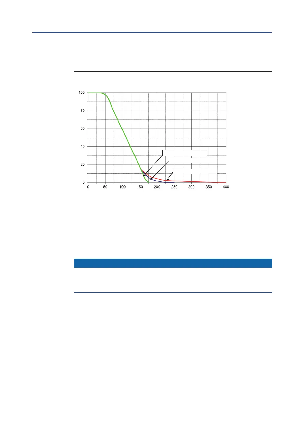
Angular stroke/quick operation time diagram
Angular stroke %
Time (ms)
Two by-pass valves open
One by-pass valve open
Two by-pass valves closed
Figure 15 By-pass Action to Angular Stroke / Quick Operation Time Diagram
Remove the protection cap from adjusting needle-valve and turn it clockwise to increase
throttling-action and consequently to slow the last part of cylinder stroke. To decrease
throttling-action, turn the needle for by-pass in anti-clockwise direction .
To reduce more the operating time (higher speed) unscrew both By-pass screws
(see diagram in Figure 15).
NOTICE
T
o correctly calibrate the quick operation time it is necessary to arrange the data acquisition
using a position transmitter and an ascillographic recorder compatible with required time. If
specic signals are built on by specic instrumentation please refer to dedicated documentation.
3.4.1 By-pass Adjustment